• Please review our updated Terms and Rules here

TV Typewriter replica project back on track

Yeah, I'm thinking I'm going to need something a bit more durable. I was trying to get this thing together for a photo shoot and video, but until I get this darned encoder to work reliably that's not going to happen. Might as well take my foot off the gas now and get something more permanent.
 
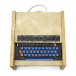
So I think if I don't get this encoder fixed today I am going to build a new one. It's just totally buggered and I cannot make heads or tails of it. The only keys that work are those that produce 1's for the first three bits (B1-B3). If I type A, I get a @. If I type N, I get an H.

I've really, really tried to read the schematics and understand what is going on, but just as I was never able to master math, I cannot understand how it works enough to properly troubleshoot it. It makes no sense to me that bit 1, which is high by default, goes low when A is pressed. I don't *think* the keyboard is at fault.. I've gone over it several times looking for wires that aren't where they should be, etc.. but no dice. Just as a last resort, I'm going to totally disconnect it and try running the encoder manually.

I've kind of wanted to redo the encoder anyway - it's on modern PCB stock and kind of sticks out. The quality of my etching at the time was pretty poor. I've only let it live this long because it was my first project, and until now was working.
 
Did a bit more checking. Found an evidently bad 2N5129 transistor. When I swapped it with another, the ringing my logic probe was getting off the first 3 bits stopped, and suddenly every key would type again.

Still not quite there.. there is still a light ringing on the @-G line. I've replaced all the diodes along that line and gotten the noise down but not out. A comes out as D now.
 
I'm gonna redo the encoder. I cannot figure out why it's flipping things around. I suspect more bad transistors.. diodes have all checked out fine. Same with the ICs.

This is ok.. now I can have all the PCBs in this thing with period correct PCBs. I can also improve the artwork for a better transfer... the first one I did, not knowing what i was doing, I just printed off the artwork in greyscale. Made for messy and weak traces. This time I'll do it as a 2 color bitmap and thicken up traces that look like a problem waiting to happen.
 
ASCII encoder attempt 2, this time with vintage PCB stock and white toner transfer silkscreen.

20180826_210533.jpg

Not bad! Only snag I'm running into with the white toner is that its properties are a bit different than regular toner. It seems to absorb some of the ink from the magazine paper I'm using. I was able to remove a fair amount of it with a light scrub, but unfortunately some of the white toner comes off with it. If I could find pure white magazine paper I'd be laughing.

The white toner also seems to go on a bit less opaque than black toner would.
 
Ok so I spent four hours building the second encoder and got it all finished. I did a test by connecting @-G to 001 and the resulting code was an A. I then connected Keypressed and all the address lines to the TVT, connected the keyboard's @-G keys and 001 keys.. typed an A.. no problem.

I then started to reconnect the other binary and key lines, powering up between each to check. Unfortunately I hit a snag.. A had turned into C. Basically anything connected to 001 was coming out 011 instead. I noticed the @-G wire was a bit loose where it connected to the encoder and did a better solder job.. suddenly A was working, as were other keys. Again proceeded forward to connect more... powered up... nope. Back to producing 011s again for @-G keys connected to 001... though any other key worked.

I let the thing sit turned off for a bit while I puzzled over it.. powered on again.. suddenly A was working. Connected more lines.. back to C.

Clearly something is flaky here. Given that it will work sporadically after sitting off for a bit.. I can only guess that one of the transistors maybe is not doing its job consistently. Incidentally, for some reason my logic probe still picks up a lot of noise on A-G. Doesn't seem to affect operation for keys not connected to 001 though.

Strange. More checking out later.
 
So, it's a strange one - I fire the thing up, and everything that uses the 001 line is messed up.. A comes out as C, etc. But I've noticed if I take my soldering iron and heat up the side of the switch on A that 001 connects to, suddenly A starts working again for a bit. And then it goes. Bad switch? Bad wire? Very weird.

I'm also having an issue where shift is applied even though the key itself is not pressed and the pin it connects to is not high/active. I thought I fixed this by swapping out a 7818 in IC1 - it started working normally.. but then on a subsequent power up shift was stuck on again.
 
Got it!

I found a tiny bit of solder that had just barely crossed from one of the 9818 pads to the trace beside it. I removed and perma-SHIFT went away!

I then set about looking for the 001 turning into 011 issue. I thought diode d6, 7 or 8 might be my problem. It was not. It was D10... one leg had not gotten soldered in fully. Once that was soldered properly, A started working again. We'll see if it lasts, but yeah. I think this beast is ready to go into her housing now, where I'll have another chance or fifty to break it again.

Definitely glad I redid the encoder. Looks so much better on vintage green PCB.
 
Dunno if this will help, but I'd be lost without my Optivisor (I use the DA-10 power one). Maybe it might be of use to you for inspection. For SMT, I use an inspection stereomicroscope. Otherwise the frustration isn't worth it.

You can get them on Amazon or eBay and lots of other places.

OptiVISOR.jpg
 
My tactic is to put my big magnifying glass lamplight underneath the PCB and look. But it doesn't help for flux bridges. I've been reading and they say to clean flux with just isoprophyl? I didn't think that would work.. the flux hardens to a sap consistency. Minute flux bridges have wreaked havoc with the main TVT.

At least it's working for tonight. :)

20180828_220732.jpg
 
Depending on what's on the board, I use denatured ethyl alcohol for flux removal (seems to work faster than isopropanol) or perchloroethylene (very fast, but a little hard on plastics). Mostly, I leave the flux on--it's an insulator and not corrosive.
 
She is finally in her case. I don't know how I could be almost 1/2 inch longer than the prototype and still have everything be this tight -- but it is! And man, is it heavy! I did not expect it to be that heavy!

I didn't really think about how I was going to place the ASCII encoder in the case. I didn't give it quite enough leash to tuck it up the side away from the power supply, and it sticks out from the bottom anyway. So I used some electrical tape for now to suspend it from the rear of the memory board.

20180829_221346.jpg

Another oddity is when the unit is laid flat, the cursor control develops a problem where it skips lines as you type. When I have the unit on it's side it's fine.

Anyway, I managed to type out my magazine cover message one more time!

https://www.youtube.com/watch?v=7dI_ISq3UDg

The final bits are to track down that issue, get some rubber feet for the case, and then get the badges and switch legends made. No idea how I'm going to do those. Right now i'm just glad it's in it's case.
 
I decided for now to print off my TVT badges on an inkjet. I'm actually surprised at how nice they came out. Here's a few snaps including a side by side:


tvt-replica-top.jpg tvt-withlabels.jpg

And side by side with original on left:

tvtssidebyside.jpg

All in all, I can't be too displeased. When I started, I had no skills working with wood, or building anything electronic. To have something that looks pretty darn close to the original (if I say so myself) is pretty satisfying. And unlike the original, it actually works!

If I find out that the badges on the original are metal I will consider ordering a set from a professional shop somewhere. But after handling my printed labels, I honestly can't really tell the difference.

Thank you to everyone who helped along the way. On to the next project. What shall it be... hrmmmmm.. :)

Note - I accidentally attached a photo of the top of the unit from CHM below. I deleted it out of my message but can't get rid of the 'attached thumbnails' garbage.
 

Attachments

  • tvt-top-profile.jpg
    tvt-top-profile.jpg
    85.7 KB · Views: 2
Last edited:
Decided to try out my 'new' Motorola 9" TV with the TV Typewriter. I was amazed at how clear the reception was! Unfortunately the cursor board is acting up again (I think). It's typing all over the place - cursor is sometimes there sometimes not, and sometimes doubling up on characters. I will figure out what's going on another day.. but for now..

20181110_193549.jpg 20181110_193553.jpg
 
Well, I'm not sure that it was ever published, which sort of limited its appeal; you could get it at one of the Byte Shops (remember those), but that's as far as marketing went, AFAIK.
 
I've found lots of other boards Electronics Associates made.. just not that one. I think boards like that will have a low survival rate if they're not with the original box/packing materials. They just look like random computer components. HoJoPo posted one he found while evaluating equipment for a non profit: http://www.vcfed.org/forum/attachment.php?attachmentid=46434&d=1530414301

Looks like it was never set up! I offered to buy but I only saw his post months after he posted it.
 
Back
Top