falter
Veteran Member
It looks like the motherboard has +5v, -5v, +12 and -12, so I'm guessing the board would have a regulator to drop to -9v. I will explore ot once it is here.
") ...
...I have a 'raw' disassembly now. It looks good. I compared it to the hex dump we had previously, and only one (1) byte stood out as different. I tracked this down to a fault in my spreadsheet and corrected it.
I am now going through the code and:
a) Comparing it to my original hand disassembly and
b) Comment the code the best I can.
Dave
I was following your other machine with 1702A's and see you found another with similar 1702A's Where are you finding these things.
When I was first trying to read 1702A's, I made a simple board with a dip switch and LEDs to read the data. It takes about 20 minutes to read all 256 locations.
I have a small bench supply for the voltages.
I now can read 1702As with my SIM4 setup. It is still slow as it is in BPNF format over 110 baud. It takes about 5 minutes to read 256 bytes.
Dwight
Wow! I didn't expect such rapid progress! Thanks Dave! I was just thrilled to see this board appeared to work, and that I now have a way to dump 1702As. Let me know if you see anything that resembles a prompt.. anything we should be looking for on the Microkit that indicates it's at least trying to run the ROM.
I've still had no luck on software. One fellow reached out but the tape he had had been overwritten. It seems to be a very rare machine today, despite evidence it was produced for a time.
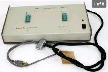
The programmer is definitely for 1702as.. I have an original catalog for it. But for sure I'll open it up and take some pics. It's quite large for what it is. I also have a homebrew 1702a programmer that I bought with the digital group card but no cables and no idea how it worked.
I didn't think CP/M was available on tape. Hmm. I'm not sure if I'm picking the right starting address to start at either. I should 'dump' it to pictures and if others want to figure out the deal with it that would be cool.

I saw this at their shop the the other day. it is in very nice condition. I don't think they have anything else though.@falter
Old thread but saw this on ebay.
Crazy price but maybe has some tapes or something useful.RARE MICROKIT-8/16 8080 LOT SERIAL NUMBER FREE SHIPPING | eBay
No export of any kind even via third party. Sale will be cancelled if attempted.www.ebay.com