Upcoming Events:
- VCF South West - June 14 - 16, Davidson-Gundy Alumni Center at University of Texas at Dallas
- VCF West - Aug 2 - 3, Computer History Museum, Mountain View, CA
- VCF Midwest - Sept 7 - 8 2024, Schaumburg, IL
- VCF SoCal - Mid February 2025, Location TBD, Southern CA
- VCF East - April 2025, Infoage Museum, Wall NJ
-
Please review our updated Terms and Rules here
You are using an out of date browser. It may not display this or other websites correctly.
You should upgrade or use an alternative browser.
You should upgrade or use an alternative browser.
Cromemco dazzler replica project
- Thread starter Hugo Holden
- Start date
daver2
10k Member
IC 42/3 is definitely wrong (although I do have a headache and I am getting ready for an early night).
We will have to do this the 'hard way'... Can you measure the following pins please:
IC43 pins 2, 5 and 1.
IC44 pins 2, 5 and 6.
IC44 pins 12, 9 and 8.
Dave
We will have to do this the 'hard way'... Can you measure the following pins please:
IC43 pins 2, 5 and 1.
IC44 pins 2, 5 and 6.
IC44 pins 12, 9 and 8.
Dave
daver2
10k Member
Hmm,
The US Patent is different to the Dazzler implementation.
I am just wondering if what you are seeing is correct?
I will have to do a little circuit simulation.
It may be helpful to switch the machine to 2 MHz just as a test to see if we exorcise the ghost and then we can look in more detail at the timing.
I think I am going to call it a night now, and I will catch up with the traces tomorrow.
Dave
Hugo Holden
Veteran Member
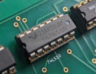
I mentioned in the past that, the newer versions of supposed 74 series IC's are often re-labelled other family parts, and that one way to tell, if it is a genuine TTL is to look at the output pin voltage swing (if there are no pull ups), if you look at IC 42 pin 6 recording, the amplitude of the pulse is near 5V, so that IC cannot be a genuine TTL part.
It is interesting a timing error like this because it could be that the enable signal is late with respect the clock signals. Or the clock IC52(2) early (relatively) with respect to the enable. IC52(1)
It is a matter of deciding which is probably the "normal" signal, which I think likely is the enable IC52(1), because it is essentially synchronized with the computer's phase 02 clock (they call it but the system clock on pin 24 of the bus PHI) and if the propagation times in this circuit were on the short side, it could only help time advance the enable signal and help the recovery of the first pulse. If this is the case, the pulses feeding IC 52(2) are arriving too early with respect to the enable on pin 1 of IC52.
Pin 6 IC8 specifically, that is the one where the pulses were deliberately delayed by Cromemco with 560pF capacitors on both this gate's inputs. If the IC's driving those capacitors, do not have a standard TTL output stage, the delay will likely be much shorter and time advance the pulse chain. I think that delay was put there to delay the pulses with respect to the clock signal on pin 24 of the bus, to ensure the first pulse in the chain was fully captured by the circuitry of IC's 41,43,44,42,52 .
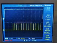
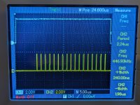
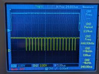
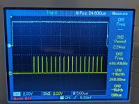
(One thing to consider again, with the digital scope, I have seen this effect many times, the ghost pulse that "appears" to be varying in amplitude and coming and going, when it is not actually doing that, may well be a full height pulse, but narrow enough that the sampling partially misses the pulse at times. For example, if you look along the sides of the other pulses in the chain, the recording with the ghost pulse post #636, you will see that the scope is interpreting them as changing in amplitude in a similar manner, due to the time differences of the sampling. It would need a much higher sample rate to check that first pulse. But having said that, the first pulse would still be suspiciously narrow in width)
I think that the circuitry of IC43,44,42, 41 is essentially a more elaborate variant of the classic pulse synchronizer. Where you to need to output a signal which is not initially synchronized to the system clock. The outgoing pulse stream becomes synchronized to the system clock edges.
Last edited:
I mentioned in the past that, the newer versions of supposed 74 series IC's are often re-labelled other family parts, and that one way to tell, if it is a genuine TTL is to look at the output pin voltage swing (if there are no pull ups), if you look at IC 42 pin 6 recording, the amplitude of the pulse is near 5V, so that IC cannot be a genuine TTL part.
Good thing a replacement for the 74LS10 (IC42) will be among the devices DeltaDon is providing, I should have in a couple of days. By this weekend I will have swapped out all the newer chips with proper vintage ones. I'll try checking for that ghost pulse at a higher sample rate.
Hugo Holden
Veteran Member
can you look at the buffered clock on IC44 pin & 11 These flip flops will be getting clocked so rapidly that the data changes on their data inputs will appear at their outputs with very little delay.
Hugo Holden
Veteran Member
Interesting, that 4MHz is the bus clock frequency in your computer.
In my SOL which is where I used my Dazzler it was the 2.045 MHz option for the standard 8080A CPU. So we know for sure that works for the Dazzler.
(the SOL can have that or 2.386 or 2.863 for the 8080A-2 or 8080A-3 CPU's as an option).
But a 4MHz clock ? I wonder if it says anywhere explicitly that the Dazzler works with a 4 MHz clock option, it probably would be expected to work ? I had not given this any thought, but it could possibly create some timing differences.
Last edited:
daver2
10k Member
I think those traces are pretty conclusive.
I would suggest leaving the machine at 2 MHz for now and we will have a think about the issue. Slower devices may help here though, and we can retest at 4 MHz then.
You should be able to carry on with the testing at 2 MHz then...
Dave
I would suggest leaving the machine at 2 MHz for now and we will have a think about the issue. Slower devices may help here though, and we can retest at 4 MHz then.
You should be able to carry on with the testing at 2 MHz then...
Dave
Hugo Holden
Veteran Member
I think a formal re-write of the Cromemco test protocol is indicated. Also to include scope grabs.I think those traces are pretty conclusive.
I would suggest leaving the machine at 2 MHz for now and we will have a think about the issue. Slower devices may help here though, and we can retest at 4 MHz then.
You should be able to carry on with the testing at 2 MHz then...
Dave
daver2
10k Member
I was proposing this previously, but I think we are now finding the faults as we go - and more!
The scope traces will be a great addition, as will be a better explanation of what is going on and why.
It is great that we have full time zone coverage from the States, Australia and the UK - global working...
Dave
The scope traces will be a great addition, as will be a better explanation of what is going on and why.
It is great that we have full time zone coverage from the States, Australia and the UK - global working...
Dave
daver2
10k Member
So, I have put together a simple model of the circuit.
Interestingly, the model has a 'ghost pulse' as well!
Also, occasionally, the last pulse can be a 'runt'. It is always there - it may be truncated. This MAY be down to the modelling system though.
Online simulator: https://www.falstad.com/circuit/.
See attachment for the model if you want to 'play'...
Dave
Attachments
Last edited:
Ok, proceeding @ 2MHz
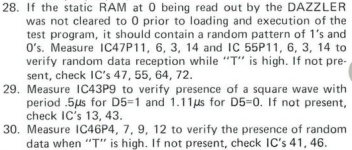
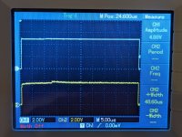
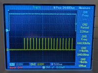
28. I'm not exactly sure what I'm looking for on this step. I guess there's random data but it seems "more random" when "T" is low.. This is IC47/14 (all of the mentioned pins look something like this):
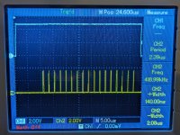
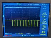
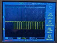
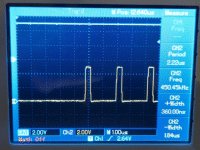
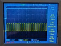
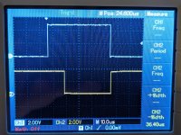
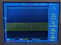
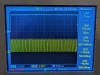
29. I see the square wave, but it's double what the test expects. D5=0: period of 2.23us, D5=1: period of 1.11us.
D5=0:
D5=1:
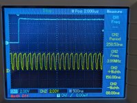
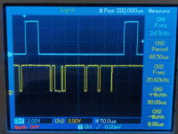
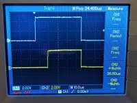
30. This doesn't look random, all pins look the same, they go high (with a delay) with T goes high, and falling edge in sync. This is IC46/9:

28. I'm not exactly sure what I'm looking for on this step. I guess there's random data but it seems "more random" when "T" is low.. This is IC47/14 (all of the mentioned pins look something like this):

29. I see the square wave, but it's double what the test expects. D5=0: period of 2.23us, D5=1: period of 1.11us.
D5=0:

D5=1:

30. This doesn't look random, all pins look the same, they go high (with a delay) with T goes high, and falling edge in sync. This is IC46/9:

daver2
10k Member
28 and 29 look OK.
As you say, 30 not.
I'll take a look after I have been fed!
Dave
As you say, 30 not.
I'll take a look after I have been fed!
Dave
daver2
10k Member
Can you check IC46 pins 1 and 15 please.
Dave
Dave
daver2
10k Member
Those pins are OK.
Can you now check that you have a good connection between 0V and +5V for IC46 pins 8 and 16 respectively.
If so, can you replace IC46 - it is probably toast.
This may account for the completely white screen.
Dave
Can you now check that you have a good connection between 0V and +5V for IC46 pins 8 and 16 respectively.
If so, can you replace IC46 - it is probably toast.
This may account for the completely white screen.
Dave


