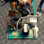
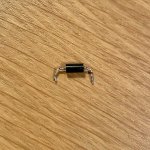
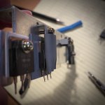
Spent some other time on this desperate case. The signal FSRD on J208.2 is sent by the DC board and goes briefly up, but soon after the safety circuit kicks in and cuts the current. I have thoroughly inspected almost everything and everything looks fine. Now, according to the service manual, the current is cut in case of shorted triac Q101 (Page 2-26 “Protection against short-circuited Q101“). I tested it and to me it seems OK, too. But maybe it’s indeed NOK. So, next week I will try to replace both the triac and the solid state relay, as I could easily source both.
Upcoming Events:
- VCF South West - June 14 - 16, Davidson-Gundy Alumni Center at University of Texas at Dallas
- VCF West - Aug 2 - 3, Computer History Museum, Mountain View, CA
- VCF Midwest - Sept 7 - 8 2024, Schaumburg, IL
- VCF SoCal - Mid February 2025, Location TBD, Southern CA
- VCF East - April 2025, Infoage Museum, Wall NJ
-
Please review our updated Terms and Rules here
You are using an out of date browser. It may not display this or other websites correctly.
You should upgrade or use an alternative browser.
You should upgrade or use an alternative browser.
NeXT 400dpi laser printer restoration
- Thread starter powerlot
- Start date
I came to the same conclusion, my Q101 triac tested fine too. So far your printer is exhibiting exactly the same behaviour as mine. I didn't pursue further troubleshooting of that circuit... that would be a sneaky fault if those parts have gone bad despite testing good
I’d be surprised if the triac was faulty, but I’m running out of ideas. As it costs little money, I will give it a try.
My understanding is that it’s either the heater circuit that for some reason is draining too much current triggering the safety circuit, or it’s the DC board that senses something wrong and switches off the printer. In such a case, it could indeed be whatever. What keeps my hopes alive is that the printer did work fine, then one day did no more, but without any catastrophic event in between. So, I still hope that the damage is indeed very localized and confined to some aging-prone kind of component. To be continued…
My understanding is that it’s either the heater circuit that for some reason is draining too much current triggering the safety circuit, or it’s the DC board that senses something wrong and switches off the printer. In such a case, it could indeed be whatever. What keeps my hopes alive is that the printer did work fine, then one day did no more, but without any catastrophic event in between. So, I still hope that the damage is indeed very localized and confined to some aging-prone kind of component. To be continued…
That's a very useful comment, thanks. By quickly searching about the SX issue, a faulty triac seems to be a likely issue behind the PSU failure.The contemporary Canon SX engine was notorious for power supply failures. I wouldn't be surprised if this engine suffered the same problems.
So, bad news: I replaced the triac and the solid state relay and unfortunately nothing has changed. There were some good hints online about Canon SX failures due to the power supply, but it seems as though here we have a different issue.
In the small clip linked here, you can see what happens (or does not happen) when I power up the printer. In the same channel you can find a short video showing the correct start up (same printer, just before this nasty fault occurred).
Any additional idea is welcome.
In the small clip linked here, you can see what happens (or does not happen) when I power up the printer. In the same channel you can find a short video showing the correct start up (same printer, just before this nasty fault occurred).
Any additional idea is welcome.

Al Kossow
Documentation Wizard
Has a Canon SX engine service manual shown up anywhere? CX is easy to find, I've been looking for an SX manual for years now.
Does your NeXT unit's fuser look like this? https://www.ebay.com/itm/111786459736
Apparently the NEC SIlentWriter II Model 990 and Model 260 used the Canon UX engine. Maybe a source for fusers.
Apparently the NEC SIlentWriter II Model 990 and Model 260 used the Canon UX engine. Maybe a source for fusers.
Another chapter of this endless saga.
Took some time for going through the AC unit. I tested all I could possibly test and to me everything seems to be in working order.
Interesting to note: as 24 V are fed into the unit via J151-1, the fan automatically starts at low speed (there’s a voltage regulator which limits the voltage to approx 11 V).
As you send some 3.5 V to the fan control pin J151-4, the diode Q158 shorts the voltage regulator (zener diodes) and the fan can spin at full speed under some 23 V (short video here).
In my case, the fan now is not spinning at all, means that there’s no voltage supplied by the DC power supply.
On to this one…
(No voltage, also means no possibility to trigger the relay and to feed current into the heater.)
Ruud
Veteran Member
I don't have any interest in printers except as using them as a printer. But I admire it that you want to repair one and I hope to read one day: "IT WORKS !!!"
So good luck!
So good luck!
Thanks for your words of encouragement! Totally agree, printers are quite boring stuff. This one is really catching me, though, as it did work until all of the sudden it just went on strike. I am now engaged in this fight, sometimes I feel like those gamblers who have lost everything and they keep on sinking money because they have the false illusion they can recover it. At least I keep on learning something, power supplies are still "understandable" (at least, to an extent...) even for someone fundamentally illiterate about electric engineering like myself (I have studied a lot of physics and electromagnetism back at the time, but very little practical applications).
So, I guess I have a Mosfet which is not OK, it didn't pass DMM testing.
Incidentally, it seems to be the most thermally loaded component of them all. So, I will try to replace it.
Additionally, on the daughter board there are two diodes (D20 and D18) next to a former leaking capacitor (C47) which have heavily corroded leads and need to be replaced (one has literally a deep crack in the lead, almost severing it).
However, there's no indication on the case, or maybe there was but then it got wiped out by the leaked stuff.
Would you have any suggestion?


andy
Experienced Member
When testing a MOSFET out of circuit, always momentarily short all three pins together to make sure the gate is discharged. It's easy for the gate to pick up enough voltage to turn on the MOSFET making it look like it's shorted.
Some update on this never ending puzzle. After some time I had the possibility to further investigate the issue. I managed to re-wire the connections of both AC and DC unit to the main board, in order to have access to all pins and run some measurements with logic analyzer and multimeter.
Originally, I though it was the overcurrent safety circuit controlling the fuser unit on the AC PSU to trigger the cut off, but in reality what is happening is that the 24V line goes down just 3 seconds after the power up signal PCONT is fed into the printer.
PCONT is wired at PIN 7 of the DC supply, it’s a 3.7V signal coming from the logic board (in turn, from the CPU through the interface board) and it triggers an opto decoupler, giving way to the high voltage current downstream the rectifier.
The 24 V should then feed the 5V DC PSU unit (the small board linked by wiring).
The PCONT signal last exactly 3”.
After that, I guess the 5 V should be available to power up the logic board and keep the whole thing alive. But there’s no 5 V, the output pin of the regulator is totally dead.
During those 3” the 24V circuit seems to get sufficiently energized (can’t measure the exact voltage, though, it’s too brief), for closing the relais of the fuser circuit (which closes and feeds current to the connector of the fuse) and spinning the cooling fan.
But as the 3” are over, the PCONT signal goes down and the whole thing becomes numb.
You need to unplug and wait for the capacitors to discharge for resetting the unit.
Honestly I cannot tell whether there’s a fault in the switching PSU controller (the IC on the daughter board), in the 5V voltage regulator, in the transistor which modulates the input voltage to the regulator or whatever else. I’m kind of shooting in the dark.
As they are cheap and available components, though, I will try and replace all of them. To be (hopefully) continued...
Last edited:
Thanks for the update.. that's an interesting find. I'm still backlogged with other projects and things in life but since I don't want to give up on this printer I'll follow this thread closely. I hope I find some time this year to jump in on this topic again
