• Please review our updated Terms and Rules here

NeXT 400dpi laser printer restoration

So, after replacing the IC and the voltage regulator in the daughter board, nothing has changed.
At a further check, it seems as though it is in fact the 24V psu which is not working. It temporarily provides sufficient voltage for triggering the relais and spinning the fan, but not enough for the 5V PSU to come alive. With my multimeter I read around 4-5 V at the 24V lines, so way too low.
I am just speculating, though. The brief moment during which something happens is so short (less than 3 seconds) that it's impossible for me to gather additional solid evidence for narrowing down the troubleshooting. Without a working unit at hand, it's indeed difficult.
I will try to find a way to trigger the unit even without connecting it to the printer, in such a way to rule out the logic board and speed up the investigation on the PSU alone.
 
You can just try feeding a current limited 24v supply into the 24v rail on the printer and see what happens.

I suspect you have a short somewhere, which is why the rail is down to 4-5v.
 
So, something strange but interesting happened. Today I dedicated some 30 minutes to the printer. I would like to unbundle the power supplies from the the printer, I need to understand if the PSU is per se good or not. When the printer starts up, it seems to me the only trigger is a 3.5-ish volt on rail 7 of the DC PSU. I could not catch any other activity on any rails during this initial step. Rail 7 seems to be linked to opto couplers, which are in turn linked to an obscure Sanken "SI-9509" component. Quite unbelievably, there seems to be no documentation at all on line about this very component. Seems to be an IC for controlling the switching PSU 115V > 24V, though. Anyhow, I tried to soft start the PSU by providing a 3.5 V signal on rail 7, but without success, nothing was happening.
Curiously enough, though, as I reconnected all the rails of the PSU to the printer and attempted to start the printer again using the main CPU, quite surprisingly the PSU sprung back to life and remained operative (you can tell it, as the fan spins, first at full speed, then it goes low) for some ten seconds or something. It was then switched off, as the fuser was not connected and the logic has it that without response from the fuser the unit is switched off.
Any further attempt to restart the unit, though, miserably failed, displaying again the same behaviour (the fan spins, then ito goes dead after 3 seconds).
 
Based on that, you can rule out any kind of major fault like a shorted power transistor, or bad power supply driver IC.

Depending on how much capacitor leakage there was, there could be some subtle damage from that. Maybe an open resistor, or electrical leakage on the board if it wasn't cleaned well enough. I had a similar experience recently with a Mac LC power supply. After cleaning, and recapping it, it worked fine for a while, but then started shutting down. In the end, I had to remove some components to clean under them more thoroughly.
 
It can be a huge problem. One check I like to do is to probe various spots on the board with an ohm meter. Any reading at all means it's not clean.
 
So, something strange but interesting happened. Today I dedicated some 30 minutes to the printer. I would like to unbundle the power supplies from the the printer, I need to understand if the PSU is per se good or not. When the printer starts up, it seems to me the only trigger is a 3.5-ish volt on rail 7 of the DC PSU. I could not catch any other activity on any rails during this initial step. Rail 7 seems to be linked to opto couplers, which are in turn linked to an obscure Sanken "SI-9509" component. Quite unbelievably, there seems to be no documentation at all on line about this very component. Seems to be an IC for controlling the switching PSU 115V > 24V, though. Anyhow, I tried to soft start the PSU by providing a 3.5 V signal on rail 7, but without success, nothing was happening.
Curiously enough, though, as I reconnected all the rails of the PSU to the printer and attempted to start the printer again using the main CPU, quite surprisingly the PSU sprung back to life and remained operative (you can tell it, as the fan spins, first at full speed, then it goes low) for some ten seconds or something. It was then switched off, as the fuser was not connected and the logic has it that without response from the fuser the unit is switched off.
Any further attempt to restart the unit, though, miserably failed, displaying again the same behaviour (the fan spins, then ito goes dead after 3 seconds).
So, a few months on…
I finally managed to source a replacement for the 24V Switching Regulator IC, the totally elusive and undocumented Sanken SI-9509.
I was very optimistic, but… no way, same as before. First start after reassembling the whole damn thing, everything fine for a few seconds. From the second start up on, just a brief pulse of life before it goes quiet.
Note that in between one has to literally pull the plug for discharging the capacitors and resetting the status.
I honestly run out of ideas, could even be that the logic board is toasted, but without a know working PSU it’s impossible to tell…
 
So, I may finally have some interesting new clue on this nightmerish topic.

Yesterday I was just about to reassemble my printer and finally store it away as “irrecoverable”, when I decided to give it a last go and out of the blue I decided to run a very simple check which - in hindsight - I should have probably run as first.

I unplugged the connector which feeds AC current from the AC PSU to the lamp and I connected my tester, as I wanted to make sure that current got fed at the right time during the printer start up sequence in the first place.

And, to my utter surprise, I found out that there was always tension, even with the printer off.
I removed the AC PSU, connected it to the mains and I could read some 100 V at the outlet plug (I run 110 V).

Which is strange and according to the service manual shouldn’t at all be the case, as there's a relais that should act like a switch.
So, this could explain why the overcurrent sensor circuit is alway triggered and is constantly and immediately switching the printer off, setting it in safe mode.

Now, I can only speculate that there must be something shorting and bypassing the relais in the AC board.
I proceeded in reverse and… I could only isolate the outlet plug from the mains connector when I removed the spark quencher SQ101.
Swapping SQ101 with SQ102 doesn’t improve the situation, though.

So, either they both are defective (they look perfect and they test open), or I am just again misstepping.
I have ordered some spare parts, in the meantime I’d be grateful if someone more skilled and knowledgeable than me could assess the situation based on the above description.

Thanks in advance for sharing your thoughts.
 
Last edited:
Does your lamp get hot then when you plug it in? Are you sure it's the full AC current you're seeing and not some measuring quirk?

1723475953021.png


1723475801264.png

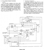
From what I understand RL101 is normally closed but Q101 outputs the AC current based on SSR101 signals.

Can you measure the /FSRD command?

I'm still too backlogged for taking this printer out of storage, but I'll eventually get to it. I'm also looking out for a second unit to compare against but they're not too commond and if they pop up, way too expensive.
 
Are you sure it's the full AC current you're seeing and not some measuring quirk?
This morning I did some trials, and I confirm I completely missed the point: it’s just a measurement quirk, so to speak.

I used two voltage regulated psu: one outputting 24 V and connected to the relais, one at 1.5 V and connected to the optocoupler (pins 5-6 and 1-2 of the comb connector, respectively). Plus a whatever bulb as resistive load, simulating the heater lamp (not with the same power, though).

With the relais open, the triac off and no load, you can still read full voltage, because of the two spark quenchers in parallel to the relais and the triac, on the hot and cold rails.
But there’s no current, the bulb is dark.
If you connect the load, the voltage goes down to some 8 V.
As you shut the relais, the bulb feebly twinkles (still some 8V).
As you close the triac, the voltage goes to the same value as the mains and the bulb lights up to the fullest.
At that point, some small voltage is proportionally generated at the terminals of the overcurrent transformer, which is feeding this AC signal to the AC control board (pins 3-4 of the comb connector).

So, the DC PSU is always under tension and, as the printer is switched on, it starts supplying +5V, -5V and +24V.
+24V are then (also) fed to the AC PSU triggering the relais and keeping it closed. The hot side of the circuit is thus established.
The triac is controlled by the logic board, closing the circuit on demand (FSRD signal) and allowing current through the heating lamp.

So, forget about the previous post, I should have studied more before posting.

I will now try to attach the AC safety board / fan control board for checking what happens, if it triggers the forced switch off.
 
So, by playing with the voltage regulated PSUs and with the light bulb, I could run some additional checks on the AC unit.
Fundamentally, nothing happens if I apply a voltage to the FSRD pin of the interface to the logic board. However, I can control the light bulb full on / off if I apply 1 V to the base of transistor Q152.
So, I’d say the circuitry labelled in the diagram as “SSR Driver” which is bridging FSRD pin with Q152 is probably at fault.
In fact, at a quick check the transistor Q151 seems to be busted, now heading out for finding a spare…
 
So, no luck so far. However, I think I am narrowing down the issue (at least I hope so!).
Below what I have recorded by direct measurement, I hope someone more skilled in electric circuitry than myself can find some useful hints.
When the printer starts up, the FSRD signal is sent by the logic board to the AC PSU for feeding AC to the heating lamp.
I can read some 2.5 V input for the FSRD through J151-3.
However, nothing happens, the triac Q101 never gets triggered, because - in turn - the optocoupler SSR101 is never triggered.
The SSR101 is controlled by the voltage provided by J152-1 and 2.
In fact, the voltage between this two pins is curiously very unstable and negative, it tends to keep on drifting towards -1.5 V.
If I supply 2.5 V at FSRD, nothing happens.
At the base of Q151 the voltage is always 0.7 V and remains fixed no matters what happens with FSRD.
However...
I can get line AC at the fuser plug (I tested the AC PSU on a bench, so I simply attached a light bulb) if I do either of the following:
- I supply 1.2V at the base of Q152
- I ground the base of transistor Q151 (found out by accident)
Under either of those conditions, the voltage between J152-1 and J152-2 goes to 1.2 V sharp and the optocoupler triggers the triac.
So, I’d guess the FSRD signal should trigger this condition, but it just does not happen. The circuitry seems to be almost passive components, everything looks intact and in order but the fact that the voltage J152-1 and 2 is not stable may suggest some defective element somewhere...
 
So, yet another entry in this endless and so far hopeless story.
I have checked all the passive and (active) components in the AC PSU and they all seem to be healthy. For sure, all caps are within the specs, so are the resistors and the transistors.

FSRD is sent by the big IC labelled “A”, via two “driver” chips 74LS07 and then directly to the AC PSU.
As they are dirt cheap, I replaced the two 74LS07 ICs, but to no avail, still stuck at the same point.

When the printer is powered up, the 24V, 5V and -5V rails get powered up. The fan starts spinning. A few instants later, FSRD is sent to the AC PSU.
The triac Q101 starts conducting (if I swap the fuser with a simple light bulb, the bulb lits up for a brief moment…), but then the current is immediately cut and the printer enters into safe mode (you have to diconnect it from the mains and wait for the caps to fully discharge).
According to the manual, this should be the sequence of events that happens in case of shorted Q101, which clearly is not
So, either the safety circuit is defective (there’s a voltage comparator on the board, which might be involved, but it also tested OK to my best knowledge), or the logic board is cutting the power for some other reason, by shutting down the 24V rail on the DC PSU…

Anyhow, it’s a very interesting topic, but as I see no real progress I am not sure if I am willing to continue down this path…
Again, without a working unit and without the missing documentation, it’s indeed like shooting in the dark…
 
The triac is driven by an opto-isolator, triggered by the FSRD signal.
As for the safety circuit, as far as my understanding goes, it acts on the relais. There’s a transformer which is monitoring the current that goes to the lamp. If the current exceeds a certain (?) amount, then the safety circuit is triggered and the relais goes open, preventing high voltage AC from feeding the lamp.
Mind though: if the 24V supply shuts down, the relais will also open. So, there are two conditions which can drive the relais open: a triggered safety circuit and/or the 24V rail going dead. Now, by logic, if the safety circuits kicks in, the 24 V supply should still be operating, but it is not, as the fan also stops.
However, so far I could not understand if the 24 V getting shut down is the cause of the effect. The thermistor is in fact feeding some input to the logic board.
So, I may speculate that in case the thermistor is feeding back rubbish to the logic board, then the logic would be to shut down the printer altogether, starting from the 24V PSU. The thermistor tested within the specs, though. Still shooting in the dark…
To be continued (maybe)…
 
There’s no sufficient uptime for detecting if the fuser starts glowing. However, I don’t think it’s the point.
The lamp tests some resistance and is not open.
Additionally, when I attach the light bulb it briefly glows before the printer goes off.
Note that the fan is powered by the same 24V rail as the rest of the AC PSU, but is controlled by an independent circuit, so the safety circuit that controls the relais does not interfere with the fan.
However, what we experience is that the fan stops, too, means that there’s no longer 24V: I would conclude that the relais opening is the effect and not the cause.
So, what is causing the 24V rail to go off?
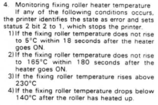
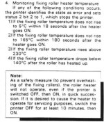
Could be a wrong reading from the thermistor, which would be compatible with condition nr 4, which would also explain why the printer goes on safety mode and cannot be restarted before switching it off for 10 minutes.

IMG_0380.jpeg

However, I already tested the thermistor once and it has a variable resistance which goes with the temperature. And the baseline value is in line with the specifications declared in the repair manual of the Laser Printer II.
Next time, I will try to catch the voltage at the connector between the logic board and the fuser, just to see what is going on…
 
Back
Top