• Please review our updated Terms and Rules here

11/70 mounting panel/support

iainmaoileoin

Experienced Member
Joined
Dec 24, 2014
Messages
216
Location
inverness
I have an 11/70 front panel - but not the complete computer ;-(

The panel has been beagleboned with Jorg Hoppes kit.

The unit has been in a portable/luggable case for a while. I now want to fit it into a DEC rack. I have BA-11 cabs and bits and pieces, but I cant find in the engineering manuals anything that describes the detail of the metal plate that goes between the panel and the cabinet. I have looked at dozens of web photos but just cant get the detail that I want. The best I have found is Appendix A (page 299) of EK-11070-MM-002 (May79) but it does not show enough details.

Sure, i can knock something up, but it would be better to make something closer to the original - rather than bits of string and chewing gum.

Does anybody know where there is a decent photo/tech drawing of the mounting plate? I assume it is similar to the /45s etc.
Thanks in advance

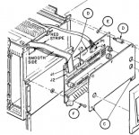
Your problem is that the front panel do not mount to the rack. The front panel mounts to the CPU box. And the CPU box is a rather large piece of hardware, which you obviously are missing.
 
nae CPU box - aye you are right

nae CPU box - aye you are right

Indeed I am missing the complete 1170 CPU box, but I do have lots of BA11s and other redeployable PDP kit.
There is a "plate" that is used to mount the circuit board onto the cabinet and then the bezel on the front of that. I cant get any pictures with enough detail to allow me to have one fabricated.

It seems to "stick out" more at the bottom than the top - this means that the power switch (which sticks out about an inch behind the circuit board)
does not foul anything.

I think you missed my point. The front panel *mounts* to the CPU box, and nothing else.
Any number of BA11 will not help you. The circuit board is not mounted to the cabinet, it is mounted to the CPU box, along with the rest of the front panel.

You're on your own if you want to try to mount the panel directly to a cabinet. DEC don't have anything for you to base your thing on.
 
I disagree - to a point - there is a metal plate (shown on page 299 of the EK). This plate holds the circuit board (via spacers). The plate then appears to fit to the CPU cabinet. Then the bezel fits to the plate.

I dont have a cpu cab, but I am sure I could fabricate the holding plate if I could get some photo/sketch of it. Sure I may have to put some additional mounting holes to fit a ?BA? box. It will never be real, but it will do for the visitors to the museum.

I am currently using 1" alum U section on both sides of the panel to do the job, I dont like the exposure of the circuit board and I am not correctly supporting the board in the middle. Cant be good for it.

Ian,
I am in a similar situation, having just re-annimated a second PDP-11/70 console with Joerg Hoppe's binkenbone circuit boards. This unit unlike the first one does have the metal bezel and back plate. I'd like to be able to mount it in a DEC rack at home and when displaying the unit at a VCF event use the portable rack mount shown in the link below. Thus it would be great if the mounting hardware were both secure and easy to disconnect for show and tell.

https://www.ebay.com/itm/Raising-6U...e=STRK:MEBIDX:IT&_trksid=p2060353.m1438.l2649

I'd be interested in sharing ideas on how to do this since it will likely involve some custom hardware. Currently I'm using some cable ties but would love to have something more solid.

Best,
Mark
 
I disagree - to a point - there is a metal plate (shown on page 299 of the EK). This plate holds the circuit board (via spacers). The plate then appears to fit to the CPU cabinet. Then the bezel fits to the plate.

I dont have a cpu cab, but I am sure I could fabricate the holding plate if I could get some photo/sketch of it. Sure I may have to put some additional mounting holes to fit a ?BA? box. It will never be real, but it will do for the visitors to the museum.

I am currently using 1" alum U section on both sides of the panel to do the job, I dont like the exposure of the circuit board and I am not correctly supporting the board in the middle. Cant be good for it.

Feel free to disagree. I can only report that on a real 11/70, the front panel is mounted on the CPU box. The CPU box is then mounted on rails in the cabinet.
 
I recently discussed with another listmember the same idea of mounting an RPi'd 11/70 console into an H960. My suggestion was to fit angle brackets to the console mounting locations, and the bottom legs to a sheet of thin plywood or plastic.
Then fit lightweight aluminium C channels into the H960 so the baseplate slides in. Simply pull it out for a portable display, perhaps put some rubber feet on the bottom. The console angle can easily be adjusted this way too by bending the legs or spacing with some washers.
 
two replies 1944GPW and Matlock

two replies 1944GPW and Matlock

1944GPW: Ta I have had the unit in "disco" 19" rack mount type case at present. The equipment covers meant that the panel was transportable reasonably protected. BUT it is time to build a more static display - in something that looks more of the era. I dont want the circuit board to bend in use and thought that a plate of the type shown in this digital manual would be the best way to fly. If it was good enough for digital it will be good enuf for me!

The sheet metal work will be trivial but I cant find a
1170.jpg diagram with the dimensions of the upstands that are on the CPU cabinet. I would fabricate the upstand and bolt it to the front of the BA11. I can afford to sacrifice the BA11 for sake of the display.

The H960 baseplate - Was your suggestion built? Did it work? Were the clearances OK? I dont have a baseplate in my collection, so that slows me down.

There are a number of box designs on the internet, but none seem to try to get the panel back into a PDP11 type cabinet. I guess that is my goal.

I have a number of Digital cabinets - mainly holding RL02s - I guess I could "faceplate" it to one of them and forget the BA11s - but if I ever needed to get to the beagle, the PSU or Jorgs etc it would be a less easy job....

Does anyone have an 11/70 45 35 etc that could tell me the sizes of the two upstands? I am "guessing" 1 1/2" and 1/2" and a cardboard model seem to give the right clearance. It seems to put the panel at a fairly steep angle. As a boy I dont remember it being that steep!


Matlock
That looks like a decent bit of angle-iron! My "disco equipment" box is rather like that but encased in ABS with removable covers.
I cant find the exact bit on ebay/amazon but it came from Germany and looked a bit like this:
https://www.ebay.co.uk/itm/162382955476.
That URL will be transient - here is a picture:
disco.jpg
The cover fitted over the bezel and switches and thus protected it in transit.

I have a wee museum opening in a bunker in Inverness and - while the museum is to do with WW2 and the cold-war - but it gives me space to move kit from my house to a more public display area. Once day I will get my house back from being a PDP store!

You say you have the backplate on your 2nd unit. Can you confirm the sizes of it - I know the width, I can guess the height, it is the depths that I cant really phathom. May as well get it right if I am going to get it. I was planning 1/8" or 3/16" mild steel for the plate, it is only four folds and a bit of drilling.
 
iainmaoileoin said:
The H960 baseplate - Was your suggestion built? Did it work? Were the clearances OK? I dont have a baseplate in my collection, so that slows me down.

To my knowledge it hasn't been built, but it's so basic I don't see why it shouldn't work.
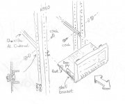
Here's a quick sketch, the idea uses the side sets of holes on the H960 rather than the front. Countersunk screws hold the 12mm aluminium C-channels and allow clearance for the baseboard to slide in and not tip up.
The brackets would need to be wide enough to reach the console mounting holes and be recessed along the horizontal leg where it impinges the channel.
slide_out_RPi_console.jpg
 
Ian,
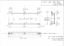
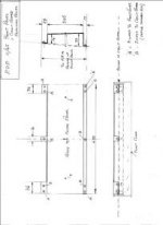
I have taken a look at my 11/45 in its H960 rack, I assume you are refering to the folded sheet metal "Top hat" section panel behind the circuit board, secured with long standoffs etc. this panel , is only a 16swg folded panel which is then bolted to the front of the large cpu frame. , if this is what you are refering to? and need any sizes or photos just pm me. I can try and help.

Harry
Seems they would need something else since they are trying to attach to the H960 rack and not the CPU cabinet. But this might make it look more "proper" once installed.
 
Ian,
I have taken a look at my 11/45 in its H960 rack, I assume you are refering to the folded sheet metal "Top hat" section panel behind the circuit board, secured with long standoffs etc. this panel , is only a 16swg folded panel which is then bolted to the front of the large cpu frame. , if this is what you are refering to? and need any sizes or photos just pm me. I can try and help.

Harry

Harry: That is indeed what I am looking for the sizes of. I can work out height and width (total) but I need some clues about the "upstand" (sticky out bit) at the bottom (circa 1 1/2" or 1 3/4" I think) and the upstand at the top (perhaps 1/2"). I will fit that panel to a BA cabinet in a standard dec rack. Otherwise the ply/mdf and alum channel would seem another way to fly. I dont mind BTUs or KW/h or mm or chains and furlongs. Any measurement units will do.

Why do I want the sizes? I would like the panels to match up with the RL02s and /or the RK05s - not to be recessed, not to stick out tooooo much.
Appreciated.
 
Harry: Thanks for the sketch. For anyone else ploughing this route of mounting a front-panel I attach the sketch of the 11/45 back plate. I assume it is the same plate as the 11/70. I will report later today it it is not the same

1145.jpg
and/or
Screenshot.jpg
 
I have an 11/70 front panel - but not the complete computer ;-(

The panel has been beagleboned with Jorg Hoppes kit.

The unit has been in a portable/luggable case for a while. I now want to fit it into a DEC rack. I have BA-11 cabs and bits and pieces, but I cant find in the engineering manuals anything that describes the detail of the metal plate that goes between the panel and the cabinet. I have looked at dozens of web photos but just cant get the detail that I want. The best I have found is Appendix A (page 299) of EK-11070-MM-002 (May79) but it does not show enough details.

Sure, i can knock something up, but it would be better to make something closer to the original - rather than bits of string and chewing gum.

Does anybody know where there is a decent photo/tech drawing of the mounting plate? I assume it is similar to the /45s etc.
Thanks in advance
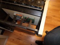
What you want/need/are looking for is the metal sub-frame on which the pcb (and the silkscreen as well as the bezel) is mounted. This sub-frame is then mounted on a BA11-F frame (the large frame).
This sub-frame can indeed be mounted on a BA11-K box, provided you will drill 4 holes in the box in order to mount the sub-frame onto it.

I also have Joergs BBB kit, see the picture (it wil also show you the sub-frame, directly behind the bezel).SAM_3899k.jpg

(I have been away a few weeks off this forum, else I would have reacted earlier).
 
Back
Top