• Please review our updated Terms and Rules here

2nd 8 inch drive

Mike_Z

Veteran Member
Joined
Dec 1, 2013
Messages
1,713
Location
Near Milwaukee Wisconsin
Today, I attempted to connect a second drive to my 8080 computer. I have recently gotten CP/M 2.2 to work with one drive. Things I did to make the second drive work was 1. added another 50 pin connector to my ribbon, 2. moved the select jumper from one drive. 3. Changed my 5 volt regulator from a 7805 (1 ampere) to a LM323 (3 ampere). Both drives will work separately, from either 50 pin connector. But when both drives are connected, CP/M will not boot from either drive. When I had the 7805 regulator there was +5.02 volts. The LM323 will only provide 4.72 with one drive connected and 4.64 with both drives connected. I have never considered what trouble low power supply voltages would cause. There is a lot of stuff on logic levels for TTL, but not much on power supply tolerances. The 4.6 volts is pretty low, at least I think so. I'm going to look into getting that voltage up to closer to +5.0. I also know that I have to change a little in the CBIOS to allow 2 drives, but I'm not even to that point. CP/M should boot with the two drives connected, or am I missing something? Mike
 
Done all of the time, Mike. Do make sure that only a single drive has termination pullups. If you have both drives with their 150 ohm pullups, the drivers may not be able to source enough current to get to a reliable "active low" logic level against 75 ohms to Vcc.
 
Last edited:
I have never considered what trouble low power supply voltages would cause. There is a lot of stuff on logic levels for TTL, but not much on power supply tolerances.
If all of the user-devices (motherboard, drives, etc.) of the power supply are known, then the norm is to examine the technical documentation of the user-devices, looking for the voltage tolerance acceptable to those particular devices. That combined information dictates the maximum voltage tolerances allowed of the power supply.

E.g.

DEVICE #1: Requires +5V within +/-10%, and +12V within +/-10%
DEVICE #2: Requires +5V within +/-5%, and +12V within +/-20%

Therefore, power supply needs to:
Supply +5V within margin of +/-5%
Supply +12V within margin of +/-10%
 
Last night after looking around some, I found those same values on the internet. That's 4.75 to 5.25 Volts. Seems the my 4.72 volts were good enough, but 4.6 volts was not. This morning I put the scope on the output of the LM323, and it was singing to beat the band. So I replaced the LM323 and tried a couple of different bypass capacitors. I got the +5 volts to behave as it should, BUT as I was removing my test leads, I sparked something. Now, the Shugart drive will not work. Fortunately the Siemens was not connected. Everything, but the Shugart work properly. So now I have to trouble shoot the drive. You know, having poor eyesight is one of the things I dislike the most about getting old. Oh well, one step forward and two back, at least today. Maybe tomorrow will be better. Mike
 
Well..... I repaired the Shugart drive. My own fault. I've made some progress in trying to figure out why I can not use two drives on my 8080 machine. I have rechecked my 50 wire ribbon cable with the new drive connector on it. There are no shorts and there is continuity. I again tried both drives separately and on each ribbon connector. Everything works fine this way.

I have removed the term resistors from the Siemens drive. Set the Shugart to be drive 0 and the Siemens to be drive 1. When I connect both drives, and try to boot, Drive 0 will recalibrate. I put the scope on pin 46 Raw Data and I can see that the drive is sending data. I can physically see that drive 0 re calibrates, then after a while will seek to the next track, then after a while the head will unload. All the time data pulse are being sent to the FDC. Yet nothing is moved to memory, no DMA function. What I noticed is that the FDC is not requesting DMA service when both drives are connected. So, I thinking that the problem, is my FDC and/or programming. What would stop the FDC from making a DMA request? Right now the only thing I can think of is, can the FDC polling a second drive cause an interrupt or something to stop the FDC from asking for DMA service? Mike
 
Before I start digging into my own code, do you issue a "Sense interrupt status" command for both drives after power up? Since you have two drives, both will issue a "seek complete" interrupt when track 0 is reached.
 
No, I don't. The routine is to set up a bunch of values, issue a SPECIFY to the FDC, A SENSE DRIVE for Drive 0, A RECAL for Drive 0 and then begin Reading drive 0, the boot. The Sense Interrupt for Drive 0 occurs at the end of the RECAL of Drive 0. Currently I do not do a RECAL for Drive 1. I can certainly add some code to do so. I'll give it a try. Do you think that if Drive 1 is not ready it maybe interfering with Drive 0 operation? Mike
 
Yes sir, then nothing. This time I think I have to modify my interrupt service routine. I've got a feeling that there maybe an overlap operation between the two drives and I'm not looking for that. Mike
 
There's always a possibility that you have more than one interrupt pending and are simply missing one. You might want to check the 8259 IRR at the end of your ISR.
 
The FDC is the only element that issue interrupts in my system. Since the system works with one drive and it stops when the second is connected, seems that maybe the second drive is causing the FDC to issue an async interrupt, which balls up things up? My ISR assumes that all interrupts are either execution phase ending interrupts or seek ending interrupts. Async interrupts are not accounted for. Mike
 
Well.... I've made some progress, but it's not clear where the problem is yet. I tried to monitor the interrupts and I don't think the problem is with the interrupts. I only get an interrupt when the FDC is busy with a read or when the seek occurs. I believe the problem is with the Siemens Drive. Although the Siemens will work alone as Drive A. When it is connected to as a second drive, the system fails. By this I mean the 8080 will run, but I can not boot CPM. I've tried making each drive the first or the second, no change.

Then I tried blocking RAW DATA pin 46 on the Siemens and this allowed CPM to boot from the Shugart drive as A. The Siemens was set to be drive B. In fact I tried making the Siemens drive to be #8 on the binary select, with no results. Seems odd, the Siemens was not selected nor was the head loaded. Having a disk in or out of the drive made no difference. So, I guessed that maybe the output gate to pin 48 (7438) was bad. So instead of replacing it, I have another Siemens drive and tried exchanging the circuit board. Now with the Siemens as drive B, I can boot from the Shugart as Drive A. BUT the Siemens could not be accessed. So I tried the Siemens alone as Drive A and it didn't work here either.

So, I checked all the jumper options. There are two jumpers that are different between the two boards. Problem is Siemens doesn't use shorting bars for these options. They are soldered in place. In fact the board that works as Drive A has the factory jumpers changed and it looks like it was a difficult change, the traces are a little butchered. So I'm reluctant to make these changes without understanding what I'm doing.

The Siemens is a FDD-100-8E. Jumper C, looks like when it is closed it will supervise INDEX and SECTOR (not used in this application) with READY. The board that works has an added jumper here. The other broad has it open (factory setting). I don't think that this is the problem. READY just means the disk is up to speed, the door is closed and the voltages are good. So, this should have little to do with INDEX.

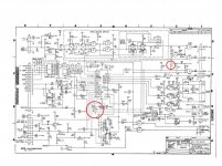
The other jumper is more mysterious, It's labeled F, G & H. There are four pads that can be connected, fashioned in a TEE. I think that the arms of the TEE are the F and H jumpers and the stem is the G jumper. This setting is a little harder to understand from the schematic. The text in the manual I have doesn't mention these jumpers. The G pad connects to an inverted Head Load line. The F pad is ground. The H pad is connected to the SELECT line. The center pad (center of the Tee) is connected to the input of an inverter which goes to a multi purpose chip input called PHASE OPT. This pad also goes to what looks like step inhibit circuitry. The manual doesn't talk about PHASE OPT (phase option?) The board that works has a jumper between the Center Pad and F the ground. So either this turns the PHASE OPT on or off directly. The board that doesn't work has the jumper between G & H. This connects the multi purpose chip output of Head Load through another inverter (G) to the center pad thru an inverter to the PHASE OPT. In other words PHASE OPT = HEAD LOAD.

I've monitored some of the inputs from my FDC. Looks like the SELECT works, the input to the head load is there, but the head never loads. The in use light on the front of the drive never lights. So, I don't know whether either board is OK. The second board may just need a jumper change. Does anyone know what this 'PHASE OPT' is? Mike
 
A few observations, just looking at the schematic in the FDD-100 maintenance manual:
  • You want radial select, not binary select.
  • With the drive unselected, but with a disk inserted, all outputs (READY, INDEX, RAW DATA, WRITE PROTECT, etc.) should be high. You should not be using DISK CHANGED--it's not used by CP/M; I don't know if you have it connected.
  • When the drive is selected, then READY, INDEX, RAW DATA should go active (you should see a low on READY and INDEX should be pulsing. When HEAD LOAD is asserted, the head should load, and you should get a waveform from RAW DATA.

If this isn't happening, re-check your jumpers. I use pairs of FDD-100 and FDD-200 drives with no problem at all.
 
I understand about the binary and radial select. I was just trying to get the drive to inhibit all the outputs. Make sure it was unselected. I do not have disk changed connected. I'll make a check on the output lines. I only partially checked them. Here is the schematic with the jumpers in questions circled. Mike

FDD.jpg
 
Chuck, I have two paper copies of the Siemens manual. One the has the Siemens name on it and that has World something printed over the Siemens name. They must have sold the line at some time. I also have a copy I found on the internet. None of the copies are dated. They all say they are Volume 1, but they are all different in small ways. Your copy is better than the ones I have. Yours explains the PHASE OPT and jumpers, where all three of mine do not mention it. I like your copy because the jumpers are labeled in the diagrams. My copies did not. I had to trace things out from the circuit schematic to figure them out. Apparently these manuals were produced at different times and were updated.

The Siemens drive that works as A: alone has the power on option at all times connected. The drive that doesn't work does not. But there is more to the story. I looked at at the outputs you suggested. The drive that didn't work did not have any INDEX pulses at all, ever. I had to adjust R34 for more current into the photo transistor. Then INDEX pulses showed up. Now both drives have index pulses when selected and none when not selected.

I also looked at the READY pulses. They are both the same. There are short negative pulses every 1 ms, corresponding to the FDC polling. The READY went low when selected.

The RAW DATA is the problem for the first drive with the modified jumpers. There are always pulses here. Without the head being loaded or a disk inserted. I'll have to look closer to find this problem. The other unmodified drive has RAW DATA always high when not selected and shows pulses when selected and a read is commanded. YET when I try to boot from this drive alone, it doesn't work. I appears that CPM is read. Two tracks, and when I do a partial check of data there is something there. BUT, the program runs wild after the boot. Maybe not a good read. So there are problems with both Siemens Drives.

I want to thank you for providing the better manual. I have to take some time to compare them to see what is there and not there. Then on to trouble shooting the drives and hopefully get one of them to work properly. Thanks for the help Mike
 
You'll note that I gave you a link to the OEM installation manual; the others are for maintenance and service. So there's different information in both.
 
Well..... I cobbled together enough parts from each Siemens drives to get one of them to work, kinda. By this I mean, the system will boot with both drives connected and both drives are recognized. I can get A> and B>. Am I correct in saying there is only one place to change in the CBIOS when adding a drive and that is in SELDSK? Is there any other items that need to be changed?

The kinda also means, all the functions on the A: drive seem to work properly, but not on B:. At the onset a A>DIR B:, resulted in NO FILES, but later after trying other combinations of DIR and STAT on B: the computer reported finding files that are on A: as being on B:. I checked and there are no files on B: Also, the files reported are reported as being there 8 or even 16 times. After powering down and trying again other A: different files were reported on B:, not consistent. Making progress, but seem to be on the road of road blocks. Mike
 
Last edited:
I suspect you're trying to be too clever by half in your code.

Again, the only sure-fire way to ensure that the disk I/O will work is to store the parameters from SELDSK, SETTRK, SETSECT and SETMDA until a READ or WRITE is called for, then do the operation as requested. HOME is simply a SETTRK of 0.

Note that the CP/M CBIOS spec does not state in what order these routines are called from either a user program or the BDOS.

If you're using sectors larger than 128 bytes, things get somewhat more complicated, but not overly so.
 
No doubt. I've tried to save each parameter, but maybe I was not up to par on the DISKNO. We will see.

Regarding the number of disks on the system. I can only find one spot where that is checked, in SELDSK, is that correct? Mike
 
Back
Top