• Please review our updated Terms and Rules here

2nd 8 inch drive

Geezzz, well doing nothing is the easiest from a programming stand point. I suppose that, you mean, before opening a door, make sure all is done, then open the door and do what is needed and reboot, starting again. Did you meet Gary Kildall? What kind of person was he? Mike
 
From what I can recall, Gary was a nice guy; OTOH, you wouldn't want to tangle with Dorothy.

What we ended up doing in our OS was to track files opened (unlike CP/M, you really did have to issue an explicit open to access a file) and if any were open when a disk was removed, give an error message and refuse to continue until the disk was re-inserted. On 8" drives with AC spindle motors, you can monitor the ready status of any disk all of the time; on 5.25" with DC spindle motors that can be turned off, not so much. We monitored the state of the write-protect sensor--when you pulled a floppy out, it would see the edge of the floppy and let you know that something was happening.

We never did figure out what to do when the person turned off the computer in the middle of a disk write, however. :)
 
Over the past week or so, I've been having a boat load of hardware problems with my 8" drives. A couple of capacitors failed, a belt broke, two more head pad flew off, one got caught in the AC drive motor and a few other items. In the mean time I picked up another Siemens FDD-100 drive. They said it didn't work, so I got it cheap. So I connected it up to my test box. First it didn't have a head pad, image that. Next the head was not loading properly, the J5 plug was plugged into J4. After I fixed these and changed the jumpers for my purpose, I could get the drive to select, and the head to seek correctly. There were no read pulses at all. So I fiddled with R100 again. I preset it to the same resistance values as my other Siemens drive that works and all of a sudden there were read pulses, but I could not get it to function correctly. It would not work with my 8080 machine, or 22DISK or IMD. The speed test on IMD would not work, yet I have nice index pulses at the correct spacings. I saw these on my scope. So I checked the write protect, and ready lines they are working OK. I looked at the read pulses with my scope and tuned R100 for the best read pulses. I then compared read pulses of this Siemens drive with the other one that works and the Shugart. They all look similar, yet the drive that doesn't work has a little larger ringing.
View attachment 24052
This a read pulse on the Siemens that doesn't work
View attachment 24053
This a read pulse from the Siemens that works
View attachment 24054
This is a read pulse from the Shugart

The difference that I see is that the ringing on the bad Siemens is a little larger. Maybe one of the crests is being seen as a high? I was also concerned about the negative swing, but they all have them, so......

I can't figure why this new Siemens will not read any ideas or suggestions. Thanks Mike
 
I'd start by double-checking the spindle speed. I was sorely bedaferated on one occasion by a 50Hz 220V drive--the spindle turned even at 120V 60Hz, but the spindle speed was all wrong. I managed to fix it by swapping in a new drive pulley and running the motor from 240V 60Hz.
 
Well, I checked the labels. The one on the drive side says 115 volts 60 cycles. The motor says 115/230 50/60 cycle. I measured the pulley diameters on both drives and they are the same size. With the scope I measure the index pulse to be 1.5 ms wide and the pulses were separated by 166 ms. So I think this is not my problem. I rechecked the ready, it stays high until selected then goes low. The write protect stays high until the disk is removed. Track 0 goes low when the head moves to track 0. The read pulses are there on all tracks, yet when I do the analyze function on IMD, track zero will read some but not all, track 1 will read all sectors and report maybe 50% error, so will track 2, then track 3 and beyond will degrade until there is nothing at about track 8. The speed test will not respond at all. It will wait a few seconds and then go back to the menu. Although I have good index pulses, the IMD speed test must look for track addresses or something like that. I think tomorrow I may swap circuit boards between the good and bad Siemens drives. That may tell me if the head is OK.

Bedaferated is a good word. I think I understand what it means. Mike
 
Did you check the alignment? It doesn't take much to put one of those off--just some idiot loosening the positioner stepper screws will do it. That would explain the odd results that you're getting.

FWIW, I've had to "un-adjust" one of my FDD200 alignment to read a customer's floppies.

IMD's RPM test simply reads the same sector over and over again.
 
I was thinking along those lines also. I have never tried to align something like this. I'm a little concerned from the fact that most times I do something like this, I generally screw it up and it take 2 days to get it back to the starting point.

From what I understand there are two alignments for the head. Radial, which sets the head directly over the head and a squareness which would set the head in parallel with the track. Have you done an alignment? Could I just loosen up the stepper motor a little and see if I can just slightly move the assembly in or out a fraction?

I did compare the head waveforms between the two Siemens drives and they look similar. I was concerned with some ringing and noise, but they both show it. I can see mis-shapened sine wave. It seems to have the most peak to peak voltage on track zero and decreases as the head moves toward 77.

I still want to try swapping the circuit boards and see if the bad drive board works in the good drive. That most likely would point to an alignment problem. Thanks Mike
 
Loosening the retaining screws on the positioner stepper and tweaking it slightly one way or the other is the way to go. Before you start, however, mark both the drive body and stepper casing...it doesn't take much to change things radically and you really need a reference point.
 
Loosening the retaining screws on the positioner stepper and tweaking it slightly one way or the other is the way to go. Before you start, however, mark both the drive body and stepper casing...it doesn't take much to change things radically and you really need a reference point.

True. I've done it without a reference point (5.25" drive) and it's doable, but it takes a long time. Also, if you don't have a disk meant for calibration (I didn't) the way that works best seems to be to adjust it to read a commercially produced disk, then try another and keep moving it back and forth slightly until both disks can be read without errors (I used a disk imager to check this with my drive, since it reads in the whole disk). That dramatically improved my data recovery ability for all my 5.25" disks after it was done.
 
Using a known-good floppy, the "quick and dirty way" is to continuously issue READ_ID commands and display the results--when you get a full track of IDs that read correctly, you can stop there. IMD has such a facility.
 
Well, this morning I read the alignment stuff in the manuals and I was all prepared to attempt an adjustment. Before I did so, I swapped the circuit boards and the GOOD drive board worked great in the bad drive frame. SO I'm pretty sure the alignment is not the problem. The manual talks about an alignment disk. I was thinking that If I could make a disk with just zeros or ones saved on it, maybe I could sync the scope so that I could see the data burst. Maybe I can see if some data is not there. What do you think? Mike
 
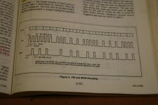
Well, any old single-density formatted disk, regardless of data should work. FM is so simple, it should be pretty easy to scope out. You always have a clock bit (except for certain ID address marks), followed by a data bit (1 or 0). You'll get a pulse for every clock bit and a pulse for every "1" data bit.

So what can mess things up in this scheme? Well, the other board works, so it isn't problems with the head or alignment, so that leaves timing and noise. Well, noise should be pretty simple, as it doesn't fall on nice neat time intervals. Timing is mostly going to be in the form of dropping pulses.

The place to start looking is IC 1E, the MC3470. Fortunately, you have a good FDD100 with which to compare signals.
 
Last edited:
It really doesn't matter--data is going to go by so fast that you won't be able to make sense of the data anyway. What you will be able to see is the pulse spacing, which should be pretty uniform.
 
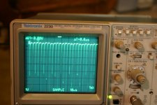
Here's a data trap that I got. Looks likes a bunch of zero's and ones. Looks like the spacing is pretty good. What do you think?
IMG_0077[1].jpg
Looks like it starts out with a bunch of zeros, then a couple of ones, etc. The pulse lows are not all the same, I wonder if that could be a problem. Maybe not all the clock pulses are being seen.

The FM bit cell is 4 usec. Looks like that there are a little more than two cells in the 10 usec divisions. The ground level is the seconf major grid line from the bottom.

Mike
 
I'm monitoring Pin 8 of chip 6C, which is the same as Raw Data pin 46. Here is the good drive with the same scope settings. I caught a bunch of zeros.
IMG_0078.jpg
If you ask me they are pretty similar.

What puzzles me is why isn't there some gaps between these pulses? Mike
 
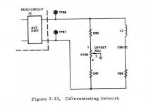
Well, I'll be a (fill in the blank)! I started to compare wave forms and resistance readings between the good and the bad boards, when I was surprised to see that C36, an 1800pf capacitor was missing from the board. It's small and easy to miss, but it was gone. Someone un-soldered it and yanked it out. So I borrowed a capacitor from one of my failed boards and soldered it in. Amazingly, the drive came to life and passed all the IMD tests and I could format and transfer files with IMD and 22DISK. Just for fun, I thought I'd look at the Raw Data that I was monitoring and comparing to the good board. It looks exactly the same, or at least as far as I can see. Maybe this capacitor, which is part of a series resonant circuit, is needed to filter out something. Obviously it is essential. Go figure. Thanks for the help, Mike.
 
I was reading the Siemens manual again, and C36 is part of a differentiating circuit. Apparently it converts the flux reversals to zero crossings. Then these zero crossing are made into 1 usec pulses. At least that is how I understand it. I guess that the circuit was still making pulses, even without C36, but they were not where the flux reversals were and therefore was just garbage. No wonder the FDC could not read it.
Diff.JPG
Amazing, Mike
 
Back
Top