• Please review our updated Terms and Rules here

6850 ACIA interface troubles

Christoffer

Experienced Member
Joined
Oct 15, 2014
Messages
299
Location
Denmark
Here I am again, with a hardware development project.
I'm building a semi-altair-compatible 8085 computer, based on the europe card bus (ECB) standard.
So far I've made a CPU card, 4K SRAM card, and a 8800B-turnkey-ish card featuring monitor ROM and a serial port.
The goal is, at first, to get that card running the altair turnkey monitor.

And I've run into a brick wall in getting the ACIA to communicate. I made it run a small test routine, that should just display some characters, and then mirror any characters you send to it.
But it won't reciprocate my sent characters. I assume it's not receiving them, but I can't for the life of me figure out why. I've traced the rx signal all the way to the ACIA (null modem'd of course) - but it doesn't react to it at all.

Here's the code:

Code:
0001   0000             ;***************************************************************
0002   0000             ;                       UART REFLECTOR TEST                    *
0003   0000             ;                SHOULD REFLECT ANY INPUT TO ACIA.             *
0004   0000             ;***************************************************************
0005   0000             
0006   0000             
0007   0000             SIORST	.EQU	03H		; ACIA MASTER RESET
0008   0000             SIOINIT	.EQU	35H		; 8/N/1, /16
0009   0000             ACIACR	.EQU	00H		; SIO STATUS AND COMMAND REGISTER    
0010   0000             ACIADR	.EQU	ACIACR+1	; SIO DATA REGISTER  /AT IO ADDRESS 01H
0011   0000             
0012   0000             .ORG 0000H
0013   0000             INIT:
0014   0000 3E 03       		MVI A,SIORST 
0015   0002 D3 00       		OUT ACIACR		;RESET ACIA
0016   0004 3E 35       		MVI A,SIOINIT
0017   0006 D3 00       		OUT ACIACR		;SETUP ACIA
0018   0008 3E 54       		MVI A,54H
0019   000A D3 01       		OUT ACIADR
0020   000C 3E 45       		MVI A,45H
0021   000E D3 01       		OUT ACIADR
0022   0010 3E 53       		MVI A,53H
0023   0012 D3 01       		OUT ACIADR
0024   0014 3E 54       		MVI A,54H
0025   0016 D3 01       		OUT ACIADR
0026   0018 3E 0D       		MVI A,0DH
0027   001A D3 01       		OUT ACIADR
0028   001C 3E 3E       		MVI A,3EH
0029   001E D3 01       		OUT ACIADR		;"TEST"CR">"
0030   0020             		
0031   0020 DB 00       LOOP:	IN ACIACR		;READ STATUS REG.
0032   0022 0F          		RRC				
0033   0023 D2 20 00    		JNC LOOP		;WAIT FOR IN CHARACTER
0034   0026 DB 01       		IN ACIADR		;GET CHAR
0035   0028 D3 01       		OUT ACIADR		;WRITE CHAR BACK
0036   002A C3 20 00    		JMP LOOP		;REPEAT FOREVER
0037   002D             .END
0038   002D             		
0039   002D             
tasm: Number of errors = 0

It's based on this code snippet I found: http://www.solivant.com/altair_bootloaders/index.php?album=altair_bootloaders&pagen=1

And here's the schematic:
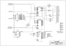
TURKEY-1REV1.4.jpg


The data/address/control signals are standard buffered 8085 signals.

When the program runs, I do get my "HELLO[CR]>" thrown back at the terminal, so I assume the rom part of the circuit is fine. Handshaking and baudrate generation must be as well.

I had some issues with driving the "E" signal since it's a thing native to the 6800 family processors, but I created that by NAND'ing /WR and /RD, again, very similar to what the turnkey card did, generating a pulse whenever it reads or writes, and I use S1 as a R//W line.

Any help with what's going on would be much appreciated.
 
A couple of points.

You seem to be initialising the ACIA with the transmitter interrupts set - but the ACIA interrupt pin isn't wired - so this will obviously have no effect. This, however, isn't the source of your problem - I just noted it in passing.

You seem to say it prints your message "HELLO[CR]>" OK - yet the assembler code (and comment) appears to print "TEST[CR]>". Have you posted the correct source code?

You shouldn't "force overwrite" the transmit data register like you are doing without checking the status register for the transmitter being free. The fact that the characters appear is probably by luck than design.

My "gut feeling" is telling me that you can write to the ACIA but not read from it (as you have already guessed). Can you explain what the 'S1' signal actually does? By adding a check for the transmitter status register being free before outputting each character of your message; you may get a clue if you can actually read from the status register or not. Bit 0 is the receive data register full. Bit 1 is the transmitter data register empty. Perhaps you need a small subroutine to check for the transmitter data register being empty before transmitting the desired character and returning. Alternatively, you can output the desired character and then wait for the transmitter data register to become empty:

Code:
TXONE:  OUT ACIADR ; Display character in A.
WAITTX: IN ACIACR   ; Get ACIA status.
             RRC             ; Get RDRF status to CARRY flag.
             RRC             ; Get TDRE status to CARRY flag.
             JNC WAITTX ; Keep looping if no CARRY (i.e. transmitter not empty = busy).
             RET             ; Return to caller.

Obviously, you will need to setup a STACK in RAM before calling the subroutine.

This may give us a clue to the next thing to look at?

I am not too sure of the 'E' generation. Can you point me at a URL containing this type of logic?

Dave
 
Noted the interrupt thing. I'll correct that, but yeah, as it doesn't react to the interrupt it shouldn't affect anything.
The hello/test thing was just me forgetting what I actually wrote. Source is correct.
You're right in the forced output thing, the code I'm going to use has proper handling of this. I should add that to the test as well.

After I posted this, I actually found the source of not being able to read from the ACIA: The DCD was pulled high, keeping the receiver in reset mode, so I added a jumper from DCD to +12V (on the RS232 side of drivers) - like the original turnkey card had. Solved it, now it reflects my characters (although double'd).

Setting up stack shouldn't be a problem, I have 4K that I'd just rather eliminate in this first test.

Since both reading and writing is working (sorta) now, I think the issue lies in the software and maybe handshaking. Tracing back the original altair 2sio interface, I've done exactly the same to E, and close to the same with S1.

S1 is a status line of the 8085 that works like an advanced read/write line: 1:read 0:write

I'll post the code I'm trying to get running, as with what you said about my test rom, it's more or less just a tad more advanced version, having all the proper read and write routines.

:
Code:
;***************************************************************
;* THIS IS A 256 BYTE PROM MONITOR FOR USE WITH THE ALTAIR     *
;* 8800B TURNKEY MODULE.  THIS MONITOR PROVIDES THE USER WITH  *
;* THE FOLLOWING FUNCTIONS:                                    *
;*                                                             *
;*     1)  MEMORY EXAMINE AND CHANGE FUNCTION                  *
;*             YOU CAN EXAMINE AND CHANGE THE CONTENTS OF ANY  *
;*             VALID MEMORY LOCATION                           *
;*     2)  MEMORY DUMP FUNCTION                                *
;*            YOU CAN DUMP IN THE ALTAIR BINARY PUNCH FORMAT   *
;*            BETWEEN ANY TWO VALID MEMORY LOCATIONS           *
;*     3)  JUMP TO FUNCTION                                    *
;*            YOU CAN CAUSE THE MONITOR TO JUMP TO ANY         *
;*            LOCATION AND START EXECUTING THE PROGRAMS THERE  *
;*                                                             *
;* THE MONITOR CAN BE REENTERED FROM THE USER'S PROGRAM        *
;* SO THAT THE FEATURES OF THE MONITOR ARE ALWAYS AVAILABLE    *
;* TO ANY USER PROGRAM.                                        *
;* EDITED FOR DIFFERENT SYSTEM BY CHRISTOFFER B. 19/04/2016    *
;***************************************************************
;
; MITS TURNKEY MONITOR
; C.W. VERTREES		01/13/1977
; REVISED		01/17/1977
;			01/19/1977
;			01/20/1977
; CHRISTOFFER B. 04/19/2016          

ACIACR	.EQU	00H		; SIO STATUS AND COMMAND REGISTER    / AT IO ADDRESS 00H; WILL BE MIRRORED AT SOME ADDRESSES.
ACIADR	.EQU	ACIACR+1	; SIO DATA REGISTER  /AT IO ADDRESS 01H
SIORST	.EQU	03H		; ACIA MASTER RESET  
SIOINIT	.EQU	35H		; /16, 8 BITS, NO PARITY, 1 STOP, NO INTS (THE BAUDRATE GEN USED ORIGINALLY IS X16: REGULATE IF NEEDED)

LEADCH	.EQU	0DH		; PUNCH LEADER CHAR
LEADCNT	.EQU	3CH		; PUNCH LEADER COUNT
SOFB	.EQU	3CH		; PUNCH "START OF BLOCK" CHAR

PROMPT	.EQU	'>'		; COMMAND PROMPT

;STACK	EQU	0FC00H
STACK	.EQU	027FFH		;middle of ram  START OF STACK IS THE TOP!!  - 4K OF RAM ENDING AT 2FFFH

.ORG	0000H		;START OF MONITOR (BOTTOM OF ROM)
MON:	MVI	A,SIORST	; RESET 2SIO  /PUT SIORST IN A
	OUT	ACIACR		; AND INITIALIZE /ENABLE INT.
	MVI	A,SIOINIT   
	OUT	ACIACR      ;SET ACIA /16, 8 BITS, NO PARITY, 1 STOP, NO INTS

ENTER:	LXI	SP,STACK	; LOAD STACK
	CALL	CRLF		; FORMAT OUTPUT
	MVI	A,PROMPT	; HELLO MONITOR
	OUT	ACIADR
	CALL	OUTCHK
	CALL	INCH		; WHAT TO DO?

	CPI	'M'
	JZ	MEM		; DO MEMORY EXAMINE

	CPI	'D'
	CZ	DMP		; DO A MEMORY DUMP

	CPI	'J'
	JNZ	ENTER		; NOT A VALID CMD

	CALL	OCTL6		; DO A JUMP, GET ADDRESS
	PCHL			; LOAD PC AND GO

; THIS CONTROL STRUCTURE HANDLES THE MEMORY
; EXAMINE AND CHANGE FUNCTION
;
MEM:	CALL	OCTL6		; GET ADDRESS

	.DB	3EH		; "MVI A," SKIP NEXT (BOMB A)
CONT:	INX	H		; INCREMENT ADDRESS
	CALL	CRLF		; NEW LINE

	MOV	D,H		; STORE ADDRESS IN D/E
	MOV	E,L
	CALL	PRINT6		; PRINT ADDRESS

	LDAX	D		; LOAD DATA
	MOV	H,A
	CALL	PRINT3		; PRINT DATA BYTE

	CALL	OCTL3		; GET NEW DATA

	XCHG			; RESTORE ADDRESS
	JC	CONT		; NO NEW DATA

	MOV	M,A		; STORE DATA
	CMP	M		; COMPARE DEPOSIT
	JZ	CONT		; OK, DO NEXT

ERR:	MVI	A,'?'		; FLAG BAD DEPOSIT
	CALL	OUTCHK		; PRINT '?'

	JMP	ENTER		; RETURN TO MONITOR

; ERROR CONDITIONS RETURN TO MONITOR VIA "ERR"
; THIS CONTROL STRUCTURE RUNS THE MEMORY DUMP FUNCTION
;
DMP:	CALL	OCTL6		; GET START

	XCHG			; STORE IN D/E
	CNC	SPACE

	CALL	OCTL6		; GET END

	MVI	A,LEADCH	; LOAD LEADER CHAR
X1:	MVI	B,LEADCNT	; LOAD LEADER CNTR

X2:	CALL	OUTCHK		; PUNCH LEADER

	DCR	B		; DECREMENT COUNT
	JNZ	X2

	CMP	B		; THROUGH WITH LEADER?
	MOV	A,B
	JNZ	X1		; PUNCH NULLS

	MOV	A,L		; SUB START FROM END
	SUB	E
	MOV	L,A
	MOV	A,H
	SBB	D
	MOV	H,A		; HL CONTAINS TOT BYTES
	INX	H		; INCREMENT TOT BYTES

BLOCK:	DCR	B		; B=FFH
	MOV	A,H
	ORA	A		; MORE THAN ONE BLOCK?
	JNZ	NOTLST		; NOT LAST BLOCK

	MOV	B,L		; LAST BLOCK LENGTH

NOTLST:	MVI	A,SOFB
	CALL	OUTCHK		; PUNCH "START OF BLOCK"

	MOV	A,B		; B=BYTE CNTR
	CALL	OUTCHK		; PUNCH BYTE COUNT

	MVI	C,0		; CLEAR CHECKSUM

	MOV	A,E		; PUNCH LOAD ADDR
	CALL	OUTCHK		; L.S. BYTE
	MOV	A,D
	CALL	OUTCHK		; M.S. BYTE

DATA:	LDAX	D		; GET DATA BYTE
	CALL	OUTCHK		; PUNCH IT

	INX	D		; INCREMENT ADDR
	DCX	H		; TOTBYTES=TOTBYTES-1
	DCR	B		; DONE W/BLOCK?
	JNZ	DATA		; NO

	MOV	A,C		; YES, PUNCH CKSUM
	CALL	OUTCHK

	MOV	A,H		; THROUGH W/ALL BYTES?
	ORA	L
	JNZ	BLOCK		; NO, PUNCH NXT BLOCK

CRLF:	MVI	A,0DH		; DO A CRLF AND RETURN TO MONITOR

	CALL	OUTCHK

	MVI	A,0AH

	JMP	OUTCHK

; RETURN TO MONITOR THROUGH OUTCHK
; THIS SUBROUTINE BUILDS 3/6 OCTAL DIGITS IN H&L
;
; SPECIAL RETURN PROVIDED BY A "SPACE", CARRY BIT SET.
; ONLY VALID OCTAL OR "SPACE" ACCEPTED. ALL OTHERS FLAGGED AND
; CONTROL RETURNS TO MONITOR.
;
OCTL6:	.DB	6		; LOAD B WITH A 6, SKIP NEXT
OCTL3:	.DB	6		; LOAD B WITH 3
	.DB	3
	LXI	H,0		; CLEAR H/L FOR LESS THAN 6 DIG RET

AGN:	CALL	INCH		; GET CHARACTER
	MOV	C,A		; STORE IN C
	CPI	' '		; COMPARE TO "SPACE"

	STC			; SET THE CARRY
	RZ			; RETURN IF "SPACE"
	ANI	0B8H		; TEST FOR VALID OCTAL

	XRI	30H

	JNZ	ERR		; BAD, FLAG & RET TO MON

	MOV	A,C		; RESTORE CHAR
	ANI	7		; STRIP OFF ASCII

	DAD	H		; SHIFT H&L LEFT 3 BITS
	DAD	H
	DAD	H
	ADD	L
	MOV	L,A		; PUT OCTAL IN H
	DCR	B		; THROUGH?
	JNZ	AGN		; NO, DO AGAIN

	RET			; YES, NORM RETURN
; THIS SUBROUTINE PRINTS 3 OCTAL DIGITS FROM H
; OR 6 OCTAL DIGITS FROM H AND L
;
; DIGITS ARE FOLLOWED BY A SPACE
;
PRINT6:	MVI	B,6		; LOAD CNTR W/6

	XRA	A		; CLEAR A
	JMP	NEXT1		; SHIFT ONE BIT

PRINT3:	MVI	B,3		; LOAD CNTR W/3

	.DB	0E6H		; SKIP NEXT, SHIFT 2 BITS
NEXT3:	DAD	H		; SHIFT H/L LEFT 3 INTO A
	RAL
	DAD	H
	RAL
NEXT1:	DAD	H
	RAL
	ANI	7		; STRIP OFF OCTAL

	ORI	30H		; ADD ASCII / 30H OR A

	CALL	OUTCHK		; PRINT IT

	DCR	B		; THROUGH?
	JNZ	NEXT3		; NO, SHIFT NEXT THREE

SPACE:	MVI	A,' '		; YES, PRINT SPACE

	JMP	OUTCHK		; AND RETURN

; RETURN TO CALLING PROGRAM THROUGH OUTCHK
; THIS SUBROUTINE WILL INPUT A CHARACTER, STRIP
; PARITY AND AUTOMATICLY ECHO THE CHARACTER.
; IT WILL ALSO OUTPUT A CHARACTER WITH CHECKSUM CALCULATIONS.
;
INCH:	IN	ACIACR		; READ STATUS

	RRC				; ROTATE A RIGHT THROUGH CARRY
	JNC	INCH		; NOT READY / BIT 0 OF REGISTER =0 (THIS CHECKS THE "RECEIVE DATA REGISTER FULL" FLAG)

	IN	ACIADR		; READ CHARACTER INTO A

	ANI	7FH		; STRIP PARITY

OUTCHK:	PUSH	PSW		; SAVE CHARACTER
	ADD	C		; ADD IN CHECKSUM
	MOV	C,A		; UPDATE CHECKSUM

LOOP:	IN	ACIACR		; READ STATUS
	RRC
	RRC
	JNC	LOOP		; READY ?

	POP	PSW		; YES, GET CHAR
	OUT	ACIADR		; PRINT CHARACTER

	RET			; FROM WHENCE YE CAME

	.END

Thanks for the help!
 
Another point to consider, if /DCD is high (not connected, dead driver, wrong flow control on terminal, et c.) the 6850 will disable the RDRF flag bit and you'll never see a character come in. In fixing a number of MITS Turnkey boards recently, this problem was usually a blown 1489 RS-232 receiver, and the problem manifested as the ROM monitor printing its prompt but not accepting input.

Assuming your 8085 board doesn't have a front panel, it's very helpful as a general debugging technique to put 8 LEDs (or hex display if you have some) on an output port that requires no initialization, like an 8-bit latch addressed directly to the bus. In this case, if you had such a display, you could alter your WAITTX loop to read the ACIA status, copy it to the debug display, and then continue on.

EDIT: Post collision! Looks like it was the DCD line, again :)
 
if /DCD is high (not connected, dead driver, wrong flow control on terminal, et c.)
Exactly what I found, thus it's now permanently (well, with a removable jumper) pulled LOW.


Assuming your 8085 board doesn't have a front panel, it's very helpful as a general debugging technique to put 8 LEDs (or hex display if you have some) on an output port that requires no initialization, like an 8-bit latch addressed directly to the bus.

I usually have that on the machines I design, but I ran out of boards this time. I've made do with using unused 74LS138 decoder outputs I can try and "write" to in memory. then those will pulse if the given part of the program is running.
 
Second post collision!

But it's still not running the turnkey code properly. besides the ACIA setup, which is identical, it should jump to the "outchk" routine and punch out the prompt character at the very least. Even if the RAM module is faulty, it should just pop garbage and send that. No reaction, though. hmm.
 
Have you tested your RAM yet? I'd write a diagnostic routine to try and get the character from the ACIA, store it in memory, clear the A register, load the character back, and then output it. You can do the same with the stack too.
 
That's a really good idea! If it can't communicate with the stack, the monitor will be fairly crippled.
I am correct in that the 8080/85 stack travels downwards, physically, so the address you set the stack pointer is is the highest memory address you want it at, right?
 
You still have an extraneous "OUT ACIADR" just after you load up A with the prompt character. I don't know if that would confuse things.

You mention about DCD. What about CTS?

Fully agree with checking the memory out first before doing much else that relies on it...

You could use a register pair (e.g. HL) as a one-level subroutine if you didn't want to use memory to start with. Load HL up with the address of the next instruction after the effective subroutine call - and JMP to the 'subroutine'. Use PCHL to indirectly jump to HL at the end of the subroutine instead of RET. You obviously can't use PUSH/POP PSW - so you will have to save/restore A to/from another register (e.g. D).

Yes, the stack travels 'downwards' in memory as you push things onto it. Technically, the SP is decremented before the first byte is stored into the stack - so you should set SP to the start of the stack memory (highest address) + 1.

Dave
 
You still have an extraneous "OUT ACIADR"
That was a slip. The ROM I'm running now is exactly the original ROM, except different IO address, stack, and ACIA control word (=15H now)
I'll just go through the RAM card hardware, then see to throwing together a mem-test routine.

What about CTS?
CTS is controlled by my terminal (pc) via Termite, and held HI, so that shouldn't interfere.
 
The 6800 parts are dynamic, not static logic, so the E signal must run continually. I now can't remember if there is any phasing requirements to read or write.

Why not use an 8251?
 
The 6800 parts are dynamic, not static logic, so the E signal must run continually.

That can't possibly be the case for the 6850 -- there are *many* vintage designs, including the MITS Turnkey board that's being simulated in this case, which don't continuously clock the E line. If the 6850 was dynamic, it'd lose its status when you stopped a system with the front panel.
 
Why not use an 8251?
Mainly to reuse as much of the altair 8800 software as possible, as I'm not an amazing assembly programmer (yet!) having lots of example code and routines to reuse is a big selling point.

Also: I had a lot of 6850's lying around.

I don't think there's such strict requirements for what E is doing, as I've seen designs (Grant Searle's 7- and 8-chip computers) that just had it tied to /IORQ of a z80, for example. Don't know if there's an upper limit, but maybe you could just tie it to the baudrate clock even.

Just tested the RAM chips, they test good in my device tester, and their /CS line jerks low on reboot (initial stack setup, probably) but there's still no serial output.
Even though it's bad practice, I'll try using the forced serial output to report back at the start of different routines so I can monitor what it's doing.

If the ACIA can TX under same conditions, but doesn't when it checks transmit data register empty, is it that the flag is set because the ACIA isn't resetting properly? IE. it's just garbage, or is it because it's not being "allowed" to transmit? - IE. a handshaking thing.

The /CTS line inhibits the "transmit data register empty" so that should be first suspect, I'd just think my terminal would handle it...
I can't see it being any other reason at this point, but I may be wrong.
 
Last edited:
That did it! tying /CTS low let it run!
I get my "." prompt, can enter M and get "M?"

Only issue is it replies my input is returned twice, like:

MM

M?

.

Thanks for the assistance!
 
Now that you've got it working, one thing you'll probably want to do is move the ACIA to I/O addresses 0x10 and 0x11 -- this is where it was on the MITS Turnkey board by default, and was also the default location for the first port on a MITS 2SIO board. This will let you run software unmodified.
 
That's thankfully just a jumper away!

The other reason I'm using the turnkey monitor is that it looks fairly simple to add commands to.
Since I have the 256 byte in a 8K EPROM, then it should be fairly easy to expand upon, but I think I'll start by seeing if I can actually load Altair basic.
 
"Only issue is it replies my input is returned twice, like:

MM"

Glad you've sorted your CTS issue.

Is it possible your terminal is setup for half duplex mode? In this mode, the terminal itself will echo any character you type and then your computer will echo it again.

If you disconnect your terminal from the computer and type a key - does it echo on the terminal without the computer connected? Don't forget you may need to sort out the hardware handshake lines to keep the terminal happy!

Dave
 
Actually, that disappeared with me changing terminal program - it also wouldn't respond correctly to most commands. HyperTerminal was better, and now I'll try my "real" ampex CRT terminal.

An interesting thing i've noticed is how dead slow it is. responds with 2 char's per second or so, even at 9600bd. I suspect this is because I severely underclocked the cpu card, at 1MHz, up to the normal 3 the 8085 would normally use.
Might also be that because of that frequency drop, the E line is being clocked pretty slowly, slowing communication
 
The communication speed should be a function of the external clock from the MC14411 and not the E pin.

I would be interested to see your schematic for the CPU part.

Two characters per second seems very slow - even if you have clocked the CPU at 1 MHz!

Dave
 
Well, my 12V supply (positive and negatively regulated wall-wart) just crapped out and died, so I think I'm stuck for tonight. aww.

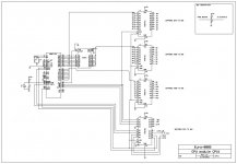
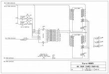
But yes, it does seem slow, here's the complete schematics:
CPU-01 REV1.3.jpgRAM-01 REV1.2.jpg

There's been a bit of change to the CPU card: All pins on the bus side is pulled up through about 15 Kohms, the buffer after the addresslatch is gone (since the latch buffers in itself) and the unused buffer in the 74LS241 is used for S1.
 
Back
Top