Hugo Holden
Veteran Member
The more I played around with the AIM-65, the more I realized (like in my SOL-20) it would be good to have extra ROM space. For example to hold small programs such as one to initialize the RM-65 video card, and or the AH5050 disk filer.
Possibly there might be some space hiding in the existing ROM's, but they are all original mask types in my AIM and I don't really want to change them.
Of course, additional memory could be added to the expansion connector, but that is currently used by the video card.
I looked at the idea of hijacking some of the upper RAM space in exchange for ROM.
There is only 4k of RAM in the AIM 65 though, that is with all the RAM sockets filled with 8 x 2114 IC's. A pair of IC's provides 1k of memory.
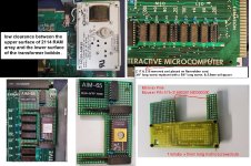
Also in the AIM-65, when the power supply is mounted in it, the bobbin of the line power transformer sits just above the surface of most of the 2114 RAM IC's and there is little physical clearance to fit a board that is taller than the IC's.
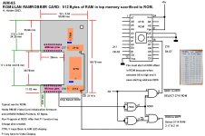
I decided to hijack (Rob) just half of the pair of 2114 IC's address space, in the upper part of memory, 512 byte addresses, from address 0E00 to 0FFF.
To do this I had to make an address decoder using the existing RAM select signal corresponding to address 0C00 and from the Address line A9.
I decided to use a 2716 ROM, simply because these are easy and run off +5V alone. It didn't really matter that most of the 2716 was not used.
I shifted the original 2114 IC's off to the side, where they were clear of the transformer bobbin. Added a 7400 IC as the address decoder to split the upper 1k address range in half and added a 2716 ROM.
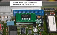
Now it is very easy to run the program in the ROM to activate the RM-65 video card, without having to load it from tape or disk. After it is run the first time it creates a linkage to the F1 key which is helpful to switch back to the video card.
I constructed it on some proto board. To keep the thin Millmax pins correctly registered I put them into a machine pin socket before soldering the array into the board. Also, I put an insulating sheet on the bottom of the board. Easy to attach. I picked up some very nice 1mm diameter x 5 mm long screws and nuts last time I was in Akeharbara in Tokyo. These screws pass through plated through holes on spot board and are useful for attaching things.
The board also screws down to an existing mounting hole with a spacer and a longer 6-32 machine screw, so that is cannot fall out.
Possibly there might be some space hiding in the existing ROM's, but they are all original mask types in my AIM and I don't really want to change them.
Of course, additional memory could be added to the expansion connector, but that is currently used by the video card.
I looked at the idea of hijacking some of the upper RAM space in exchange for ROM.
There is only 4k of RAM in the AIM 65 though, that is with all the RAM sockets filled with 8 x 2114 IC's. A pair of IC's provides 1k of memory.
Also in the AIM-65, when the power supply is mounted in it, the bobbin of the line power transformer sits just above the surface of most of the 2114 RAM IC's and there is little physical clearance to fit a board that is taller than the IC's.
I decided to hijack (Rob) just half of the pair of 2114 IC's address space, in the upper part of memory, 512 byte addresses, from address 0E00 to 0FFF.
To do this I had to make an address decoder using the existing RAM select signal corresponding to address 0C00 and from the Address line A9.
I decided to use a 2716 ROM, simply because these are easy and run off +5V alone. It didn't really matter that most of the 2716 was not used.
I shifted the original 2114 IC's off to the side, where they were clear of the transformer bobbin. Added a 7400 IC as the address decoder to split the upper 1k address range in half and added a 2716 ROM.
Now it is very easy to run the program in the ROM to activate the RM-65 video card, without having to load it from tape or disk. After it is run the first time it creates a linkage to the F1 key which is helpful to switch back to the video card.
I constructed it on some proto board. To keep the thin Millmax pins correctly registered I put them into a machine pin socket before soldering the array into the board. Also, I put an insulating sheet on the bottom of the board. Easy to attach. I picked up some very nice 1mm diameter x 5 mm long screws and nuts last time I was in Akeharbara in Tokyo. These screws pass through plated through holes on spot board and are useful for attaching things.
The board also screws down to an existing mounting hole with a spacer and a longer 6-32 machine screw, so that is cannot fall out.