• Please review our updated Terms and Rules here

Amstrad PC1640 - Faulty Floppy Disk Controller or Disk Drive

The more I think about it, the more I think IC110 is the culprit for your error message.

Can you remove the 3 jumpers (Link 1, 2,3) so that the normal hardware tests are done. Pin 2 of IC110 should go high just before you get the error message, what happens on both Pins 1 and 3 of the same IC110?

I'm guessing the interrupt high is not making it's way through this IC?

Many thanks all for your continued help with this. I think we may have solved this (hopefully). :)

I think you are right @austfox about IC110 being the culprit - but perhaps it's indirectly the culprit!

Pin 2 of IC110 starts LOW and goes HIGH before the error message.
Pin 3 starts HIGH and stays HIGH.
Pin 1 goes HIGH to LOW.

I assume Pin 3 (which is the IRQ6 signal) should be starting LOW and going HIGH to match the signal from pin 18 on IC112?

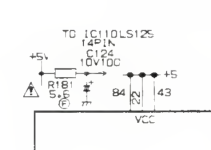
So IC110 could be faulty. However, I decided to check to see if IC110 (74LS125AN) was receiving a voltage at pin 14. It wasn't. Nearby R181 (a 5.6 Ohm resistor) is responsible for transferring the voltage from the 5V line. There is continuity between the resistor and pin 14 but there was no voltage. On the other side of R181 was a steady 5V.

Surely R181 is the culprit.

I suppose IC110 could also be faulty, but perhaps not.

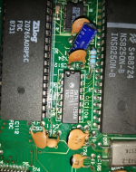
I'll replace R181 and report back. I'm pretty sure it's a 5.6 ohm resistor but I'm not sure what the (F) in a circle means underneath (image from the circuit diagram below and also an image of the actual resistor; it doesn't look too healthy tbh).
1700426378733.png 1700426661019.png
 
Last edited:
I asked ChatGPT about the 'F' underneath the resistor in the circuit diagram and it suggests there's a fuse in parallel. I'm not sure where that is. If this is indeed true, could the fuse have blown too? Would that need replacing.

Thanks!

Edit - Some more Google searches suggests that the resistor itself is fused. If this has 'blown' then might that suggest another problem?
 
Last edited:
I'll replace R181 and report back. I'm pretty sure it's a 5.6 ohm resistor but I'm not sure what the (F) in a circle means underneath (image from the circuit diagram below and also an image of the actual resistor; it doesn't look too healthy tbh).
Have you measured it ?, I just measured R181 in situ on my 1640 board and got about 6 Ohms, Motherboard NOT powered up.
 
The PC1640 electrical parts list suggests R181 is a '5.6ohm fuse'. Thanks @modem7; so this is a 5.6ohm fusible resistor.

I've found a few of these 5.6 ohm resistors but they have different power ratings. I'm not sure which I would need.
 
Last edited:
Have you measured it ?, I just measured R181 in situ on my 1640 board and got about 6 Ohms, Motherboard NOT powered up.

Thank you for this. At the '200' ohms range setting, I'm getting 125 with black on the input side and red on the other, and 106 when reversed. I assume this means it's bad.
 
Last edited:
I get around 5.8 ohms in circuit.

I had a look and they don't seem to be a common item. I would probably place a 5.6 ohm resistor in series with a pico fuse (100 mA?), maybe others could confirm?
 
Thank you for this. At the '200' ohms range setting, I'm getting 125 with black on the input side and red on the other, and 106 when reversed. I assume this means it's bad.
Correct. The difference in the two readings will be due to your measurements being done in-circuit. Being a resistor in-circuit, expected is 5.6 ohms (+/- tolerance), or less (possible less due to a resistor being measured in-circuit).

Have you measured it ?, I just measured R181 in situ on my 1640 board and got about 6 Ohms, Motherboard NOT powered up.
When powered, what is the voltage drop over the resistor? That will inform us of how much power the resistor is normally dissipating.
 
I had a look and they don't seem to be a common item. I would probably place a 5.6 ohm resistor in series with a pico fuse (100 mA?), maybe others could confirm?
I have never had one fail on me. Reading some datasheets, the fusing portion is 'slow blow' (slow acting). Maybe someone with fusible resistor experience will comment.
 
When powered, what is the voltage drop over the resistor? That will inform us of how much power the resistor is normally dissipating.
Can't power mine it's missing the monitor, My intention is to rig up a cable and plug it into an external PSU but haven't got around to it yet.
 
During the boot process (up to 'insert system disk') I don't see the voltage across the resistor go over 0.065V (12 mA?).
 
During the boot process (up to 'insert system disk') I don't see the voltage across the resistor go over 0.065V (12 mA?).
Power = 0.00076 W

Looking at the photo in post #61, if that was a standard resistor, I would say that it looks to be 1/4W. But are standard resistors and fusible resistor of the same wattage, the same physical size?
 
Thank you for all of your advice regarding this resistor. :)

When I checked the datasheet for 74LS125AN it seems to require a voltage of 5V (4.75 min and 5.25 max). Apologies - I'm a layman with the precise workings of components; why is a resistor needed at all between the 5V line and an IC that requires 5V? I'm curious as to why austfox was only seeing 0.065V across the resistor. Doesn't the 74LS125 need to be powered fully all the time?

5.6 ohm fusible resistors seem extremely rare. The closest I could find were these but there is no 5.6ohm variant. I assume the 5.1 or 6.8 ohm options wouldn't be suitable.

eBay - Link

So would a standard 5.6 ohm resistor with a fuse, in serial, be the best option? Any further advice greatly appreciated. Thank you all again; it feels like some progress is being made here.
 
The 0.065V is the voltage drop across the resistor only, the IC is still seeing 5V (I measured it at the time at it was bang on 5.01V). The resistor is there to limit the current to the IC.

If I was doing the repair, I'd order a 5.6 ohm resistor, a few pico fuses in both 100 mA and the next size up (maybe 150 or 250 mA) and probably a couple of the 74LS125ANs and see how you go.

Thanks for clarifying. I'll do that and report back. Hopefully I'll have some good news.

Do you have any advice for putting these in serial?

Would the easiest thing be to use the PCB holes where the current transistor is - adding one fuse leg first from the 5V rail side, orientating it vertically and then soldering the transistor (positioned again vertically but side by side) to the other leg ? Does it matter which goes first in sequence? Fun times! :)
 
By transistor, I'm sure you meant to type resistor. I'd mount the resistor vertically with one leg in one of the existing fusible resistor holes, and mount the pico fuse vertically in the other existing hole, and join them together above the board. They don't need to be in any particular side.

The pico fuses are fast blow, so I am not sure if that will have any effect, I choose them only because they will make for a neater install. I believe the resistor helps restrict the initial inrush current anyway.

I would replace the 74LS125 by default also, in case that was the IC responsible for blowing the existing fuse.
 
5.6 ohm fusible resistors seem extremely rare. The closest I could find were these but there is no 5.6ohm variant. I assume the 5.1 or 6.8 ohm options wouldn't be suitable.
I would have gone with the 5.1 1/4W, They have a +-5% tolerance, Like Modem7 said Did it die of old age or was it pushed.
 
Sorry, missed that eBay link above. They should be an ok replacement. I'm usually reluctant to purchase electronic components from eBay, but passives are usually ok.
 
Back
Top