• Please review our updated Terms and Rules here

Amstrad PC1640 - Faulty Floppy Disk Controller or Disk Drive

By transistor, I'm sure you meant to type resistor. I'd mount the resistor vertically with one leg in one of the existing fusible resistor holes, and mount the pico fuse vertically in the other existing hole, and join them together above the board. They don't need to be in any particular side.

The pico fuses are fast blow, so I am not sure if that will have any effect, I choose them only because they will make for a neater install. I believe the resistor helps restrict the initial inrush current anyway.

I would replace the 74LS125 by default also, in case that was the IC responsible for blowing the existing fuse.
Yes, I mean 'resistor'. :)
Thanks for your advice. I have all the parts coming. I'll keep you updated.
 
I was planning to add some headers to these 3 links so I could have a look at the various jumper settings
I was looking over my board and can see LK901-1 which is hardwired closed and LK901-2 which is open, Can't find any info on those 2 as to what they are for though ?
 
I would have gone with the 5.1 1/4W, They have a +-5% tolerance, Like Modem7 said Did it die of old age or was it pushed.

So, the 5.1 ohm 1/4W fusible resistors arrived.

Firstly, I socketed and replaced the 74LS125AN (IC110). Then I replaced the resistor. All looked fine pcb wise. Within a few seconds of switching the 1640 on, I could see smoke coming from the resistor. Off it went. :-(

So, perhaps the old resistor was indeed 'pushed'. A steady 5V was being measured at the entry point to the old dead resistor. This is correct isn't it? Why would the new one instantly fuse? Could the voltage be okay but the current is too high?

Is it worth trying the 5.8 ohm non-fusible resistors with a PICO fuse? Thanks!
 
Last edited:
So, perhaps the old resistor was indeed 'pushed'. A steady 5V was being measured at the entry point to the old dead resistor. This is correct isn't it? Why would the new one instantly fuse? Could the voltage be okay but the current is too high?
Yes, +5V is correct. Excessive current is being drawn by something 'downstream', and that is what is failing the fusible resistor - the reason it exists.

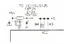
Capacitor C124 might be the culprit. Remove it, and see if that action changes anything. C124 is there to provide some noise filtering. For investigative purposes, the circuit will work without it, and obviously, you can check C124 when it is out.

1701377407190.png
 
Yes, +5V is correct. Excessive current is being drawn by something 'downstream', and that is what is failing the fusible resistor - the reason it exists.

Capacitor C124 might be the culprit. Remove it, and see if that action changes anything. C124 is there to provide some noise filtering. For investigative purposes, the circuit will work without it, and obviously, you can check C124 when it is out.

View attachment 1268847
Thank you. I'll try that next. :)
 
Thank you. I'll try that next. :)

I removed C124. The good news is that the second 5.1 ohm resistor did not start smoking. The bad news is that for some reason I'm not seeing anything on the screen now. :-(

And, although I can't see anything, I think the system is actually working now. The drive lights up, the heads move and it shuts off. If I press a key on the keyboard, the system tries to read the system disk. So, it would seem, I have reached the prompt successfully. I just can't see anything. :)

However, saying that, I plugged the PC speaker in (haven't done that before) and it was making repeated beeps. Not sure what that means.

Could removing that cap have caused the screen to not come on? I can't see how it's related.

Fun and games!
 
Could removing that cap have caused the screen to not come on? I can't see how it's related.
Neither can I.

Before (fusible resistor open-circuit), there was no +5V going to IC110. Now there is, so IC110 is now operational.

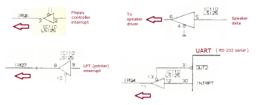
The four gates within IC110 are pictured below. IRQ6 is now working, which allows the 'floppy controller reset' to happen. The speaker now works. But nothing passing through the four gates should prevent a screen display.

Have you been playing with the motherboard jumpers or DIP switches, and forgot to restore their settings to what they were before ?

1701409591466.png
 
The LK1 to 3 links previously discussed are now back to normal - i.e unabridged. I can only think that perhaps I knocked the switches on the side of the PCB that do control monitor related display functions.

I did notice there was an occasional flash on the monitor during power on.

There are knobs on the monitor controlling brightness and contrast. I thought it might be that - but no.

It seems like the screen itself isn't powering for some reason on. Yet, the monitor itself powers the PCB.

Could the burning resistor have somehow caused damage to another part of the circuit? Seems unlikely as the system sounds like it's working.

I'll check the switches. Thanks.
 
Have you been playing with the motherboard jumpers or DIP switches, and forgot to restore their settings to what they were before ?
You were right! 😊

It was the DIP switches. I set them back to default for an MD display and it all worked. I must have knocked them.

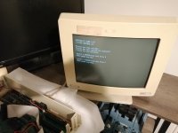
I'm happy to report that the system appears to be working - and it's displaying 640k as expected.

I can't thank you all enough for your help!

Now, all I need are some 5.25 Amstrad system disks to test further. At some point I'll investigate XT-IDE.

I summise it would be wise to replace the 100uF capacitor I removed.IMG_20231201_074225.jpg
 
That's really good news, and a relatively simple fix. Modem7's knowledge astounds me!

I notice your 1640 is running v3 bios (1987), and mine is v3.1 (1988). I have a couple of other 1640s, so will have to dig them out and have a look what they are running.
 
I'm happy to report that the system appears to be working - and it's displaying 640k as expected.
Excellent, :)
I notice your 1640 is running v3 bios (1987), and mine is v3.1 (1988)
Mine is at v3.1 also, I finally built a cable and have it powered using a ATX PSU, I'm stuck on a KeyBoard error because i don't have a keyboard for it yet.
 
Now, all I need are some 5.25 Amstrad system disks to test further. At some point I'll investigate XT-IDE.
You can find images of the system disks here (and also elsewhere): http://dosdays.co.uk/computers/Amstrad PC1000/software/download.php

However, you may also use other DOS versions (I happily used MS-DOS 5.0 for years back then). You do need Amstrad's mouse driver for the properitary mouse, and possilby also the keyb driver if you have a non us-keyboard. Other than that, everything should work just fine.
 
That's really good news, and a relatively simple fix. Modem7's knowledge astounds me!

I notice your 1640 is running v3 bios (1987), and mine is v3.1 (1988). I have a couple of other 1640s, so will have to dig them out and have a look what they are running.
Yes, you've all been a great help. It's great that there's so much knowledge out there. Thanks again for helping me solve this one.

I wonder what the difference is between v3 and 3.1 - perhaps a bug fix?
 
You can find images of the system disks here (and also elsewhere): http://dosdays.co.uk/computers/Amstrad PC1000/software/download.php

However, you may also use other DOS versions (I happily used MS-DOS 5.0 for years back then). You do need Amstrad's mouse driver for the properitary mouse, and possilby also the keyb driver if you have a non us-keyboard. Other than that, everything should work just fine.
I'm keen to use the 5.25 inch drive to get that authentic feel. Based on the guidance at the link you provided, I assume the only option (other than a Gotek) is to get some blank 5.25 inch disks.
 
Excellent, :)

Mine is at v3.1 also, I finally built a cable and have it powered using a ATX PSU, I'm stuck on a KeyBoard error because i don't have a keyboard for it yet.
Do you need an original, or are there adaptors out there for using a modern keyboard?
 
Back
Top