• Please review our updated Terms and Rules here

Another PET 2001-8 for restoration

A4000Bear

Experienced Member
Joined
Dec 30, 2010
Messages
111
Location
Taradale, VIC, Australia
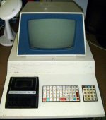
I have just received an incomplete PET 2001-8 for my collection.
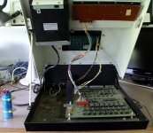
It is missing the power transformer and possibly associated parts. The large sticker on the front is also missing. I guess the kids from the high school it used to belong to ripped it off many years ago.

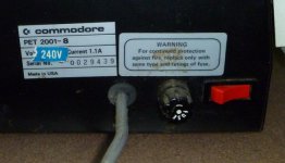
Before I attempt restoration, I'll need to know if I can find a suitable replacement transformer (I live in Australia, so it needs to be 240V, 50Hz). Failing that, does anyone know the power requirements of the motherboard and monitor?

I also understand there were quite a wide range of front stickers for the early PETs. It would be nice to know which one is appropriate for my model, so that I can have the right one made up.
An interesting feature of this machine is that the cutout for the cassette drive appears to be hand made, and rather roughly done. The cassette drive is a commodore badged unit.

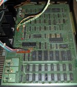
The main logic board is p/n 320132. The newest chip is dated 25th week of 1978, though the 6522 is from 1980 - I suspect it was replaced at some time.

At this stage I do not know if the motherboard and monitor is working.
 

Attachments

  • Front.jpg
    Front.jpg
    88.4 KB · Views: 2
  • Inside.jpg
    Inside.jpg
    91.6 KB · Views: 2
  • Serial.jpg
    Serial.jpg
    29.6 KB · Views: 2
  • Motherboard.jpg
    Motherboard.jpg
    98.3 KB · Views: 2
I did some testing on the motherboard this weekend, using the video mixer circuit into a separate monitor. I powered the motherboard from a 9V CT transformer I had lying around.
As I half expected, I got the famous PET corrupt screen on powerup - though with a difference. There are no PETSCI characters, only ordinary text on a white background as shown.
corrupt.jpg

I managed to test the RAMs, they are all OK, including the video RAMs. I suspect one or more ROMs are bad, but I'll need to make an adaptor before I could go any further.

I also quickly tried the board with a PET-VET installed. It works OK.

I wonder why I don't get the 'normal' corrupt screen?
 
I also quickly tried the board with a PET-VET installed. It works OK.

This is good as it may mean you only have some bad ROM (if you tested the 2114 RAMs). If you understand the PETVET mapping (which I don't) it would be possible to map in one system ROM at a time and determine which are bad.

I wonder why I don't get the 'normal' corrupt screen?

The only PETSCII codes that work is hex 30 to 3F so this may mean your character generator (A2) ROM is bad or you have stuck bits in the video RAM. PETVET can't solve a bad character ROM so you will need a ROM adapter to use a 2716 EPROM.
-Dave
 
Did a further quick test tonight.

With the PET-VET installed, I plugged in the keyboard and got the PETSCII characters to work as normal, so the character ROM is obviously OK. Still not sure why the corrupt screen I get (when not using the PET-VET) is different to usual..
I should add that I had to clean the keyboard first, not a single key was working!

The character ROM is an MPS6540-010

I'm curious.. what is the 'PET-VET' exactly?
 
It is a small board that plugs into your CPU socket. You then plug the CPU into a socket on the board. The board contains a controller with 32K RAM and Flash Memory to replace the PET main board RAM and ROM. Very useful especially for old PETs with the unobtainable memory parts. Also very useful in troubleshooting your PET memory as blocks of RAM and ROM can be memory mapped in or out to help isolate the problem chip.

See PETVet
 
Some more progress.

Got the board working without the PET-VET.
As I expected, one of the ROMS was faulty (6540-18 ). Replacing it with a substitute fitted to an adaptor resulted in normal operation.
The adaptor came from here: http://home.comcast.net/~medasaro/6540rom.com/6540romadapter.html

Close examination of the faulty ROM revealed some corrosion on some of the pins. It looks like it may have been mouse urine, which has probably wicked inside the chip.

The only remaining fault on the board is a melted (!) TIP29 transistor that drives the second cassette port.

I still need to find a suitable power transformer. I understand the PET uses a 7V centre tapped winding, and a second 14V winding for the monitor. What is the current rating?

Does anyone know what is the appropriate front panel sticker for the particular model I have? (see the original message)

MB-after.jpg

Here is a pic of the restored motherboard. As you can see I'm powering it from a spare Amiga 500 power transformer. Not ideal as the voltage is a bit high, and regulators get rather warm....but good enough for testing.
I guess you could say the A500 is helping his great-grandfather!
 
Last edited:
I still need to find a suitable power transformer. I understand the PET uses a 7V centre tapped winding, and a second 14V winding for the monitor. What is the current rating?

I do not have the details of the original PET 2001 transformer, but here is some info on the transformer for the newer universal models like the 8032 in case that may be of some help.

Transformer pins
4 and 6 => 22VAC connects to full wave rectifier which outputs +/- 9 VDC unregulated which drive +/-5V regulators (-5V not needed for old 2001 PETs as it is used for dynamic RAMs only)

5 center tap for 22VAC which is grounded to give balanced +/- 9VDC

7 and 8 => 18VAC connects to full wave rectifier which outputs +16VDC unregulated which drives +12VDC needed for dynamic RAMs

9 and 10 => 15VAC for 9" video monitor
9 and 11 => 21VAC for 12" video monitor

As far as current rating for the transformers, since the +5VDC regulator is rated at 1A, I would assume the AC windings would be rated at about 0.75A, but if the old transformer was only 7VAC than a current rating of 1A would be better.
 
Thanks for that, Dave.

It's not easy finding an exact replacement transformer.
After some poking around, and bearing in mind the types of transformers available, I am going to use two 9 volt centre tapped transformers, each rated at 60 Watts. A slightly higher voltage, but the regulators seem to cope OK.
I understand this model PET consumes 1.1 Amps at 110V, which equates to 121 watts, so 2x60 Watt transformers should be OK.

I did think about hacking a PC power supply....but then I'd have a Frankenstein monster, not a PET,

The motherboard does seem to use a fair bit of current at 5V. The ROM and RAM chips do get surprisingly warn....almost hot, but as mentioned before, all original RAMs are good, and I only had one faulty ROM.
 
Thanks for that, Dave.

It's not easy finding an exact replacement transformer.
After some poking around, and bearing in mind the types of transformers available, I am going to use two 9 volt centre tapped transformers, each rated at 60 Watts. A slightly higher voltage, but the regulators seem to cope OK.
I understand this model PET consumes 1.1 Amps at 110V, which equates to 121 watts, so 2x60 Watt transformers should be OK.

What about the need for 15VAC for the video board? The video board simply takes the 15VAC input and runs it through a full wave rectifier (4 diodes) and then to a 7812 voltage regulator chip to generate +12VDC.
If you used a PC power supply you might use the +5VDC for the main PET board and +12VDC directly into the video +12V circuit bypassing the need for 15VAC. However there would be a shared common return and maybe that would be noise on the video??
 
I was thinking of using one transformer to power the motherboard, connected as two 9V windings, and the other transformer without using the centre tap, as a single 18V winding for the monitor.
Testing has shown that the slightly higher voltage is not causing any problems. The regulators get mildly warm, not hot.

Fitting the two transformers is no problem, they are both smaller than the original, and other than drilling a few extra mounting holes, they go right in, without any other modifications.
 
I was thinking of using one transformer to power the motherboard, connected as two 9V windings, and the other transformer without using the centre tap, as a single 18V winding for the monitor.
Testing has shown that the slightly higher voltage is not causing any problems. The regulators get mildly warm, not hot.

OK, I see. Good job.
 
Restoration is now complete, though I still need to replace the missing nameplate on the front panel.
Apart from the faulty ROM and missing power transformer mentioned earlier, some of the keys on the keyboard were intermittent. This was traced to a badly terminated contact on the keyboard connector. A fault the PET would have had since new.
I also noticed there was a tiny burn on the screen. I believe this was caused by a bright spot that remained on the screen after the PET was turned off. I modified the monitor to prevent this, by changing the value of C22 from 3.3uF to 47uF. The effect of this is to hold G1 on the CRT to the voltage set by the brightness control for the few seconds needed while the cathode cools and the EHT voltage drops.

The missing power transformer was a real problem. In the end I had to improvise.
Originally I had intended to use two 60 watt 9V CT transformers, powering the motherboard from one and the monitor from the other. Unfortunately there was not enough room for them. Also, the 60W transformer that would power the motherboard got rather hot for my liking. it looks like the early ROM and RAM chips had quite a high current consumption, given they get quite warm in normal operation.

I decided to use a 160 W transformer to power the motherboard. it had two 9V windings, so the power supply circuitry was unchanged from the original. This transformer is toroidal, so it did look different to the original.

To power the monitor, I found a very small switching power supply that provided 12V 1A regulated. This was put into a very small plastic box and attached to the rear of the computer.

Front.jpg
The outside, with rust removed and repainted. I need a new front panel sticker.

Back.jpg
The rear, showing the insides of the monitor.

Cassette.jpg
I managed to clean up the case around the cassette drive a bit. It was rather roughly hacked out to accommodate a C2N instead of the original drive, which was probably replaced at some stage. Compare with the original pic on my first post.

Inside.jpg
The inside, with the rust and dust removed.

Power.jpg
The new power transformer. Compare it to the picture on my first post.
 
Chandler1, I believe you are after a UK transformer?
This is the transformer I used: http://www.ebay.com.au/itm/9-9V-160...Electrical_Test_Equipment&hash=item5d431c39b7
It's sold in Australia, but you should have no problems using it as both Australia and the UK use the same voltage, 230V 50Hz.

This transformer has dual 9V windings, which is slightly higher than the 7V original, so the regulators do run warmer than normal. Not a problem unless you want to operate your PET in a hot room.
You will also need to find a separate 12V 1A power supply to run the monitor, I used the guts out of a plug-pack (sometimes called a wall-wart) and put it in a small plastic box stuck to the back of the computer (You can see it in some of the pics)

Something like this would work: http://www.ebay.com.au/itm/Powertra...Electrical_Test_Equipment&hash=item19e11b9546
You will have to bypass the rectifier and regulator in the monitor to use this.
 
Last edited:
Back
Top