• Please review our updated Terms and Rules here

Apple ii europlus

Gary C

Veteran Member
Joined
May 26, 2018
Messages
2,302
Location
Lancashire, UK
Well, might have taken on a bit. Not only have I just got a TRS-80 model 4 ive not been brave enough to switch on, I have just received an Apple II europlus that needs a bit of tender care.

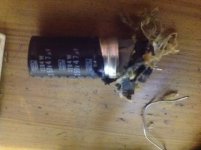
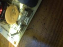
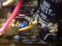
Opened up the PSU for an inspection and its decorated with capacitor remains ! so some work before I even turn it on.

Anyone have a good circuit diagram for the PSU
 
A recap will solve most problems on the apple2 supplies. The other common problems can be quickly found with a multimeter.

The failure of C6 was enough not only to blow the 2.5A fuse but to actually crack the glass ! (never seen that before)

Recap is in order but where to get them.

Found an apple spec that lists the 47µF caps as +100% / -10% and they seem hard to find in the correct format. Have some nichicon 47µF caps on order of the correct mechanical spec and electrical spec other than a tollerance of 20% (and ESR is a bit marginal on another spec i found, but thats not listed in the apple spec)

Anyone have a source ?
 
The capacitor that blew isn't the rifa cap that normally blows without killing the fuse :)

The one that blew is not critical and doesn't need to be low ESR simply increasing the max voltage rating will give a lower ESR.
I typically replace the mains filter caps with ones from ebay rated at 400v.
Just like these ones
https://www.ebay.com.au/itm/5PC-47u...796682?hash=item33ec1f270a:g:-JAAAOSwomVbFQlP

Because it was a mains filter cap that blew and took out the fuse due to a short it might have taken out the bridge rectifier also, so check that with your multimeter before you power it up again.
As I said none of the caps are critical for value, rather than the expense of paying for low ESR I just use higher voltage rated caps to get the lower ESR with a larger safety margin. The output filter caps can all be 1000uF 25v and it will work fine.
The only one that needs the correct value is C7 and I generally replace that with a 220uF 16v cap.

You can get away with using the higher voltage rating because modern capacitors are smaller than their 80's counterparts.
 
Got some 400v caps with the advantage that they are virtually the same size and colour as the originals, also got a replacement c7 at 25v on the way, but need to get a new fuse. Looks like a T2.5 20mm ? (as the glass had split, the cap pinged out of the holder and sailed into the deeper recesses of the garage) and have lots of those at work.

Rectifier seems ok on a quick check, though is showing a short N to neg, which the diagram is showing a cap across, so prob need to leave the fluke on for longer for a true reading.

Think the previous owner must have recently turned it on, cap blew and flogged it on cheap to me as each of the big caps were wet underneath so didn't look like it had been long since the failure.

From memory its a 2.5A fuse.. all my apply parts are currently packed in a box somewhere (moving house soon).

Pull the bridge and test it out of circuit. Your multimeter will just charge/discharge the caps so you wont get a valid read on it in circuit.

Yes, its not uncommon. People pull them from storage with the intention to sell them as a working machine, so the first thing they do is plug them in and turn them on, which of course is when the caps are most likely to blow.
They don't realise old capacitors degrade when not used and need to be powered up slowly with a variac to recondition them. I'm too impatient for that though, plus its cheaper for me to recap than it is to buy a variac.
 
I was wondering if it's a slow blow, hence T2.5. I imagine it would be for this application.

You can test rectifiers in circuit within reason, just one cap hiding a diode, others are fine, but I might whip it out to be sure.

Question, seems to be some debate on running the psu with no load, some say it won't work, others say it's fine.

Edit, good call on rectifier, what I was seeing measured in circuit was exactly what it shows out of circuit, one diode has gone short circuit, switching the fluke off diode still shows zero ohms from once AC leg to the negative terminal in both directions. Chicken or egg ?

Need some more time now to check other input components before power up.

This is fun. When I used to work on circuits of this age in the 80's, the parts were easy to get, now you have to spend a bit of time getting the old specs and comparing to new to make sure it's all covered

There are quite a number of KBP cased rectifiers out there with different specs, so gone for a 210, 2A 1000v, 1.1 forward drop in a KBP case, should be ok.

R1 checked and looks good.
 
Last edited:
Also check the main switching transistor, it may have been what triggered the whole sequence of events.
If Q1 looks good then I'd fit the new bridge and fuse, recap and fire it up with no load.

2A/1000v is the spec for the KBP10. 1000v is probably more than needed. The KBP206 (2A/600V) are also common on ebay at 10 for a $1

As to the PSU under load debate, anyone that tells you they dont work without a load has never tried it. I can assure you the run just fine with no load. I've repaired more than 30 of then in the last 3 years and every single one was initially tested with no load. Only when I am 100% satisfied the supply can maintain its voltage without going high do I test them under load. A switch mode power supply with a regulation fault tends to go over voltage and triggers the crowbar protection. If it can maintain its voltage with no load then its unlikely to go over voltage with a load.
 
Will check Q1 too, thanks for the advice. Will try it no load first (I couldn't see how it wouldn't work, but hey ho).

Only bought it (and others) for the fun of fixing them.
 
Well, new rectifier fitted and DC supply present but PSU not working.

Q1 & Q2 appear ok.

So while the circuit diagram on page one is generally ok, it doesnt include the details of T2 & T3 and there seems to be some anomolies. A diagram from applebox (http://www.appleii-box.de/D04_allabotpowersupplies.htm) giving a more detailed circuit and expected signals seems to disagree with the connections (specifically Q2 collector seems to be only connected to the coil in T2 in the applebox diagram where as the diagram on page 1 suggests connections between C9 & C8 and T2)

is there a definative, verified, detailed diagram of an AA11040C (or even just a B) ?

So next candidate diode? so will take them out one at a time, along with Q1 & Q2 to fully test out of circuit, but I also need to check the coil continuity and cant find a definative drawing.
 
My mistake, the test diagram I found was for the very similar Apple III psu. Still, it's hard to test using the widely available drawing for an a11040b when the internals of T2 aren't shown.

So, anyone, what forms the oscillator?, C7 is given as setting the frequency of the oscillator, but its an electrolytic and wouldn't like + & - Ve of a normal LC tank ?

What forms the parallel LC that Q1 maintains ? Also noticed that R25 is missing, read another thread where this was the same, when replaced and the psu sprang into life. R25 sit's parallel with R24 and I can see no reason why it's not there. The legs are present but under close inspection they don't look snipped but there are no debris in the case to suggest it popped. Odd.

Ageing brain gradually starting to work but needs a little help to change gear.
 
Last edited:
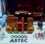
Replace C7, it is often the cause of the symptom you have. The other likely culprit is the small feedback transformer, one of the windings goes OC. Its easy to test in circuit, if one set of windings reads 68 ohms in circuit then it has gone OC. If it has let me know and I'll tell how I fix them.

R25 is one of the resistors used to adjust the 5v level. depending on the voltages the factory would cut out a resistor to set the voltage
 
Thanks

Already swapped C7 and Q1 has two good PN junctions so that looks ok. Will check Q2 out of circuit next.

Will need to have a good look with the scope on Monday when I actually have a day off.

Just trying to work out which bits form the LC oscillator.
 
It could be the small signal transistors and on a rare occasion and open circuit resistor on the primary side. However the most likely problem is that feedback transformer, 70% of the faults I get that are not fixed by a recap are that transformer.
14940108_1318136234883532_2505776855320786254_o.jpg

If it faulty you will read about 68 ohms across these terminals in circuit. To fix it wind on 30-35 turns of enameled copper wire in the same direction as the original windings and terminate the ends on the terminals marked. I've found that 30-35 gives about an output voltage close enough to spec that I dont have to mess about with the adjustment resistors.

Thanks

Already swapped C7 and Q1 has two good PN junctions so that looks ok. Will check Q2 out of circuit next.

Will need to have a good look with the scope on Monday when I actually have a day off.

Just trying to work out which bits form the LC oscillator.
 
Back
Top