• Please review our updated Terms and Rules here

BA23 power supply problems

leegleason

Experienced Member
Joined
Jan 20, 2014
Messages
239
The problem ones are starting to pile up here. I have one with 5 volt supply at 4 volts. Another one will run for 10 minute, and then the fans stop. Before I dig into these, I have a couple questions. Has anyone found or reverse engieered a schematic for these supplies? Anyone seen these particular problems? And, do I need to connect a load on these to test them outside the system?
 
>>> Do I need to connect a load on these to test them outside the system?

I am sure they are switchers, so the answer should be yes (but I don't have access to my manuals at the moment).

I am sure I have seen a reverse dissassembly of these PSUs somewhere (or was that in my dreams)?

Dave
 
I have done partial schematics of the H7864. However you need to know several things:
  1. They are done using Eagle
  2. I am not an electronics engineer, so they are not drawn logically.
  3. There are likely to be some mistakes
  4. They are partial
 
Anything would be welcome - could you package them up with a PDF version for those without eagle? - Use a large paper size if possible please..

Robin
 
I have done partial schematics of the H7864. However you need to know several things:
  1. They are done using Eagle
  2. I am not an electronics engineer, so they are not drawn logically.
  3. There are likely to be some mistakes
  4. They are partial
That's more than I have now...I'd be glad to have whatever you've got.
 
I am sure I have seen a reverse dissassembly of these PSUs somewhere (or was that in my dreams)?

I thought I also remembered something like this, but it was probably this post about a modern version of an H7864

Schematics from @rjarratt are probably the best thing for debug and repair of the authentic power supplies. Maybe the modern version schematics and a look at the PCB will help to fill in the possibly missing pieces. I haven't checked to see how similar the modern version might be to the authentic version. Maybe there are similarities that will be helpful to verify and/or complete the authentic version schematic
 
And, do I need to connect a load on these to test them outside the system?
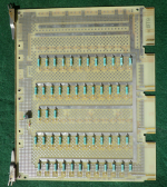
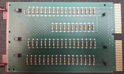
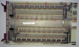
There are a variety of Q-bus "minimum load modules" (with helpful LEDs) for testing the power supply with all of the cabling into the backplane, without risking damage to expensive boards. The dual M7556 has load resistors and LEDs for +5VBB and -15V (presumably they meant -12V), and the quad M9060 can have load resistors for +5V and +12V. Note that there are a variety of stuffing options for the M9060 - the -YA variant I have is only populated for +5V. Presumably there is at least a -YB, variant with different parts stuffing. Since you won't have any other boards in the chassis, you don't need to worry about grant cards, etc. I'd stay out of the first few slots that are Q/CD and just put the load board(s) in the higher slot numbers.

Now that I'm thinking about it, I should probably just dig out the solder sucker and stuff the +12V side on my M9060 - it only needs an array of load resistors, an LED and the current-limiting resistor for the LED.
 
What value for the "-YB" load resistors? Some old notes from Noel Chiappa:

-----
For debugging power supplies, a 'load module' (a card with only a bunch of resistors on it) is invaluable. No trying to figure out where/how to connect a large load resistor - just plug the board in.

DEC made several:

M7556 dual - +5V 1A -15V 375mA
1737712553641.png
M9049 single - +5V 0.25A(!)
1737712570615.png
M9060-YA quad - +5V 5.3A
1737712579179.png
M9713-AA dual - +5V 2.75A -15V .75A (KDJ11-E Load Module for 11/94)
1737712730702.png

The M7556 (at least) can be used on both QBUS and UNIBUS backplanes (since they share the same pins for +5 and -12V (QBUS) vs. -15V (UNIBUS). Probably all the others can be used on both buses, too, but check the pins they draw from first.

The M7556 can be easily modified (with a few etch cuts) into a +5/+12V load module, but the resultant board can _only_ be used in a QBUS.

If you can't find any of these (there are none left on eBay, but other suppliers still seem to have them), another alternative is to get a blank prototyping board from Douglas Electronics (http://www.douglas.com/), and add your own resistors.
 
The problem ones are starting to pile up here. I have one with 5 volt supply at 4 volts. Another one will run for 10 minute, and then the fans stop. Before I dig into these, I have a couple questions. Has anyone found or reverse engieered a schematic for these supplies? Anyone seen these particular problems? And, do I need to connect a load on these to test them outside the system?

Just use an old IDE disk drive or two as a load for testing. Your BA23 already has the correct loom.

-Alon.
 
Just use an old IDE disk drive or two as a load for testing. Your BA23 already has the correct loom.

-Alon.
I never thought of that! I have lots of old MFM drives I can use for a desktop load. Thanks for the suggestion.
 
That's more than I have now...I'd be glad to have whatever you've got.
Here is a zip of what I have. It has been a while since I used Eagle I don't know if there are other files you need. I have included a JPG of one of the boards as the parts are not labelled so I made up my own labels and put them on the JPG.
 

Attachments

Here is a zip of what I have. It has been a while since I used Eagle I don't know if there are other files you need. I have included a JPG of one of the boards as the parts are not labelled so I made up my own labels and put them on the JPG.
Thanks!
 
Please remember it is not drawn logically, it's incomplete and probably has errors. If you do spot any errors though it would be great if you could tell me what they are. And if anyone can offer a suitable rearrangement to make the drawing more logical that would be great too. One day I plan to move all my schematics to KiCad.
 
I'd be worried about over-current on the connector fingers. Doesn't anyone know how the current draw compares to the single slot current spec?
Given that controllers like the KDA50 exist (about 7A at 5V for each quad module, 13.5A total) and the fuse on the DEQNA cabinet kit is 1.5A at 12V (powered from the fingers of a dual-width card) I don't think we're going to be blowing up backplanes here - these are cards DEC intended to be used for the purpose we're using them for. In fact, on certain configurations it was necessary to leave the load module in at all time, unless the card cage was stuffed full of other cards.
 
necessary to leave the load module in at all time
I never thought about that. I knew the VS2000 sized TK50's had a resistor board to provide sufficient loading, but I didn't realize DEC had the same issue with backplanes.

Something to keep in mind when I (attempt to) resurrect some of my basket case systems. I want to run the BA23's with CPU and Q-Bone only if possible.

CW
 
Please remember it is not drawn logically, it's incomplete and probably has errors. If you do spot any errors though it would be great if you could tell me what they are. And if anyone can offer a suitable rearrangement to make the drawing more logical that would be great too. One day I plan to move all my schematics to KiCad.
These look great, will be a big help, thanks. And if anyone else wants to look at these, but doesn't have Eagle, you can use the free EasyEda to view them.
 
Back
Top