Hello,
I recently acquired a flat Commodore 128 but with no power supply (PSU). I have a working Commodore 64 and 1702 monitor (and IBM 5153 CGA/RGB monitor) to test with. I know the monitors and monitor cables work. I have a C64 PSU which I purchased a little over a year ago from C64PSU.COM. I also ordered from them a C64 to C128 PSU adapter.
C128 Motherboard: Artwork No. 310381 REV 7 Mfg date: 11/85
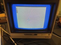
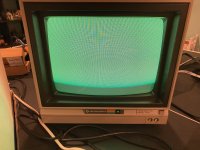
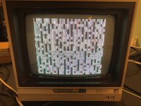
When I turn on the C128 the red power light does come on but I get a black screen. I've tested with the 1702 with a Radar Rat Race cartridge (that works on my C64), but still a black screen. I've tried testing with the 5153 monitor, with the 80 column key pressed, still nothing. I've tried all the combinations of the 40/80 column key and the Commodore key, a cartridge plugged in and not plugged in. Tried the RF connector to my TV. Still a black screen.
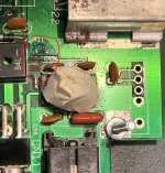
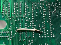
I've disassembled the machine, inspected and didn't see any bulging or cracked capacitors, broken/severely degraded traces--but some traces don't look ideal. I did spot some corrosion by capacitor C99 and what looks like an exposed trace (see pic).
I removed all socketed IC's, cleaned the pins and sprayed with DeoxIT, still black screen.
I do notice that the MOS 8502 CPU, MOS 8564 VIC composite video and voltage regulator (U59) get hot in about 5 minutes.
I've looked thru the C128 Diagnostic Instruction and Troubleshooting Manual (1986)(Commodore)[PN-314060-01] and other forum posts regarding the same black screen issue. I don't have an oscilloscope, just a manual digital multimeter. Below are the readings with the keyboard disconnected and no other peripherals connected.
The components that seem suspicious are:
CR13 rectifier
C97 capacitor
CR11 diode (possibly)
U59 voltage regulator (possibly)…not sure if testing it in-circuit is recommended/conclusive
Any thoughts as to what components I should replace or what else to test? Thanks.
I recently acquired a flat Commodore 128 but with no power supply (PSU). I have a working Commodore 64 and 1702 monitor (and IBM 5153 CGA/RGB monitor) to test with. I know the monitors and monitor cables work. I have a C64 PSU which I purchased a little over a year ago from C64PSU.COM. I also ordered from them a C64 to C128 PSU adapter.
C128 Motherboard: Artwork No. 310381 REV 7 Mfg date: 11/85
When I turn on the C128 the red power light does come on but I get a black screen. I've tested with the 1702 with a Radar Rat Race cartridge (that works on my C64), but still a black screen. I've tried testing with the 5153 monitor, with the 80 column key pressed, still nothing. I've tried all the combinations of the 40/80 column key and the Commodore key, a cartridge plugged in and not plugged in. Tried the RF connector to my TV. Still a black screen.
I've disassembled the machine, inspected and didn't see any bulging or cracked capacitors, broken/severely degraded traces--but some traces don't look ideal. I did spot some corrosion by capacitor C99 and what looks like an exposed trace (see pic).
I removed all socketed IC's, cleaned the pins and sprayed with DeoxIT, still black screen.
I do notice that the MOS 8502 CPU, MOS 8564 VIC composite video and voltage regulator (U59) get hot in about 5 minutes.
I've looked thru the C128 Diagnostic Instruction and Troubleshooting Manual (1986)(Commodore)[PN-314060-01] and other forum posts regarding the same black screen issue. I don't have an oscilloscope, just a manual digital multimeter. Below are the readings with the keyboard disconnected and no other peripherals connected.
The components that seem suspicious are:
CR13 rectifier
C97 capacitor
CR11 diode (possibly)
U59 voltage regulator (possibly)…not sure if testing it in-circuit is recommended/conclusive
Any thoughts as to what components I should replace or what else to test? Thanks.
Item to test (tested w/ keyboard disconnected) | Expected result | Actual result |
Male 5-pin DIN power plug | 5 VDC, 9VAC | 5.1 VDC, 10.7 VAC |
6581 SID (U5) pin 25 | +5 VDC | 4.74 |
6581 SID (U5) pin 28 | +12 VDC | 11.89 |
8502 MPU (U6) pin 40 0 VDC on power-up, w/+5 VDC in 1 second | +5 VDC | 4.72 |
Datasette port, pin 2 | +5 VDC | 4.74 |
Capacitor (+ leg) C107 | +5 VDC | 4.75 |
Capacitor (+ leg) C99 | +5 VDC | 3.45 |
Connector CN11 - pin 1 | +5 VDC | 4.80 |
Capacitor (+ leg) C111 | +12 VDC | 11.91 |
Anode of diode CR10 | +18 VDC | 17.48 |
AC inputs of rectifier CR13 | 9 VAC on both | 11.5, 11.3 VAC |
Capacitor (+ leg) C97 | 9 VAC | 5.28 (not sure which is + leg) |
Connector CN11 - pin 3 & 5 | 9 VAC | 10.4 |
Connector CN11 - pin 1 | +5 VDC | 4.8 (amps fluctuate 2.7 to 0.1) |
Anode of diode CR11 | 9 VAC | 13.94 VDC, 29.8 VAC Not sure if measured correctly |
Anode of diode CR15 | 5 VDC | 4.31 |
Voltage regulator IC (U59) pin 3 When testing continuity in-circuit, the ground and output pins give 193 Ohms. I assume all pins tested should test open/no reading? | 11.9 VDC | 11.93 (1.45amps) |
Z80 CPU pin 11 | + 5VDC | 4.74 |