daver2
10k Member
Post #356 - replace 244 buffer UB10...
Dave
Dave
Ah ok sorry!Post #356 - replace 244 buffer UB10...
Dave
Yes i changed only ls244 on ub10....On the assumption that all you have done is to replace UB10 then one (or more) of the following situation(s) applies:
1. The buffer you have replaced UB10 with is faulty.
2. There is a problem with the IC socket, the PCB or the soldering of the UB10 socket.
3. Another (unrelated) fault (or faults) has happened between the other day and now.
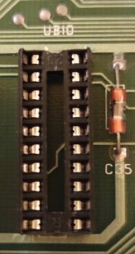
Can you post a close-up photograph of the top and underside of UB10 please?
Dave
Ok Dave i understand, i ll check all ic that i have change and i ll check continuity! Thanks so much, i ll update you very soon.... I hopeSo, I can partially see what is going on.
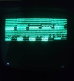
The PETTESTER V4 in post #364 actually PASSED the VDU test and then moved on to test page 0 and 1 RAM - where it failed. Read the manual... A 'g' indicates a good memory byte and a 'b' indicates a bad memory byte.
Post #370 appears to also move on from the VDU test to the RAM test - and then also fails - but the display is corrupt (both the initial VDU display and the RAM display). This sort of indicates to me that the issue is either on the VDU display side of things (not the CPU/VDU memory side) or it is intermittent - and will sometimes PASS the VDU test and other times not.
Post #371 is worse - it is not passing the VDU test anymore AND there is serious flipping of display characters.
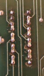
I suspect you have an intermittent solder joint, bad socket or something similar occurring - and we need to fix this otherwise we will get nowhere. Have you cleaned up the flux from the other ICs you have replaced? If not, can you do that now please. The next thing would be to continuity test from the leg of each of the ICs you have replaced to a connected point on a pin of an IC that you haven't replaced.
I am afraid this is 'slog' rather than detective work...
Dave
Can i try change ub13 socket.... We Have already had some troubles in this socket..I have just noticed on the schematics that pin 16 of the CRTC (UB13) can invert the video signal. Pins 17 and 18 also drive signals such as the CHARACTER SET OPTION and the DISPLAY ENABLE. It is not a bad connection again on some other pins of UB13 is it!?
Dave
It depends.But now must i use v4 or v9 pettester version?
I wouldn't for now. Just perform a continuity test and make sure the pins are making good contact with the PCB tracks. Let's try not to introduce more variables.Can i try change ub13 socket.... We Have already had some troubles in this socket..
Ok tomorrow i ll check continuity on ub13 pins!I wouldn't for now. Just perform a continuity test and make sure the pins are making good contact with the PCB tracks. Let's try not to introduce more variables.
Of course, I can't stop you if you want to change it can I?
Dave
If i look schematic i can t see where check continuity from pin 16,17 and 18 of UB13....I have just noticed on the schematics that pin 16 of the CRTC (UB13) can invert the video signal. Pins 17 and 18 also drive signals such as the CHARACTER SET OPTION and the DISPLAY ENABLE. It is not a bad connection again on some other pins of UB13 is it!?
Dave
 (((
(((