Chromedome45
Veteran Member
Well as already stated put me down for 1 right now.
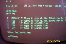
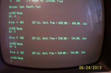
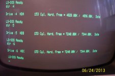
Now booting from CF card with a boot disk. The Model 4 can't boot from a hard drive unless it has updated ROMS I think. But the 4p can but not sure how it does it. So drive 0 is CF card as is drive 1 also drive 2. Drive 3 is bottom floppy and drive 4 is top floppy. Now try not to get confused with that setup! Just a test I was running. According to the HD drive manual you can set up 6 logical drives on the "hard drive".
Pearce: Just a thought maybe add an on board 5v regulator? 7805 with supporting caps etc. Then can use any DC power supply like a 12 or 15 volt unit. I added one to my prototype and usually add to all my stuff. Just a thought totally up to you to add.