• Please review our updated Terms and Rules here

Commodore 1801 crooked picture and convergence(?) issues

powerlot

Veteran Member
Joined
Nov 20, 2021
Messages
549
Location
Europe
Hello all

Something for the analog tech / CRT experts here... I've got a 1801 monitor a while ago which was incredibly dirty and a little bit scuffed outside, but looks otherwise pretty mint on the inside (there was none of that black dust you usually have inside CRTs)

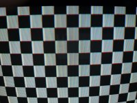
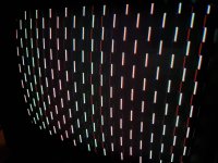
The problem with this monitor is that it produces a bright and colorful picture, but it is tilted and not as clean as on one of my other CRTs. There are visible red pixels and some shadows where there are contrasts.
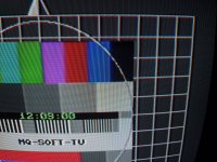
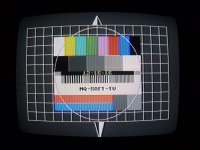
1801-1.jpg1801-4.jpg1801-3.jpg1801-2.jpg

I haven't touched a trimpot or capactor yet and before I do it, my questions are:
- How do I tilt the picture back? I hope it doesn't involve turning the yoke while the monitor is on... if yes I'd be thankful for any safety advices to reduce the chance of me getting zapped
- How to diagnose and adjust the convergence problem (if it is one)? Is the white shadow on the contrast-y also part of it or another issue?

Thanks again!
 
There is some mild barrel distortion of the raster scan and the beam convergence is off largely in the R upper corner area.

Do you have the service manual for the set ? Often this contains instructions about how to adjust these factors.
 
I found this: https://archive.org/details/manual_1801_SM_COMMODORE_EN/page/n13/mode/1up

Unfortunately I don't have any idea about these adjustments, I'll have to study the manual.

I don't have a pattern generator for the patterns in the manual either, only the patterns in the c64 TV tests prg.

I ordered plastic adjustment tools a while ago but they somehow never arrived. I'll come back to this when I'm wiser and with appropriate tools.

Any idea about the bleeding? Especially visible on the left side of the white checkerboard pattern? The barrel distortion might just be the camera up close.
The test patterns you have would be adequate. There may also be a mild purity error. Can your c64 TV tests do a plain red green & blue screen ? if not you can do those in BASIC if the version allows it by plotting a filled box.
A quick look at the manual shows they have provided a good description of the purity and convergence adjustments.

That bleeding effect you refer to is a mild defect in the video high frequency response, it could be in the actual signal, or it might be the VDU.
 
There are no obvious purity issues (the TV Tests do produce the colored screens), that's just the camera again if you're referring to the reddish / yellowish splotches in the middle of the photos.

The bleeding only happens on this monitor, I've verified it with different monitors and signal sources.

As soon as I get my tools and manage to measure and adjust B+ and the brightnesses I'll post new pictures of the test patterns.
 
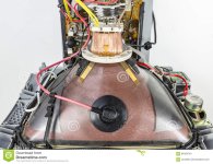
The static convergence (in the centre) seems OK, but you do have a problem with dynamic convergence. This is affected by the position of the deflection yoke. Sometimes thin plastic strips with a small piece of insulated metal on the tip are inserted in the gap between the yoke and the CRT to adjust dynamic convergence in one corner or side of the picture. You may have one that has been dislodged or fallen out. See picture below. The service manual describes how to adjust convergence, but be aware the process is rather fiddly and you will never achieve 100% perfection.

A tilted picture is caused by a dislodged yoke. It will need to be rotated back to the correct position. Note there are high voltages on the deflection yoke windings.

The 'bleeding' effects on the checkerboard pattern are caused by a 'peaky' or uneven frequency response in the video amplifiers. Check that the video cable is good quality (Never use an ordinary audio lead) and that the monitor is providing the correct 75 ohm load to the video input line. Otherwise, it is a problem that will need to be tracked down internally. Are you using the ordinary composite input, or are you using the separate chroma/luma input?

The image below shows an example of the plastic strips I mentioned earlier. There are two of them, coloured yellow and stuck down with double side tape. Your monitor may have a different number of them - or even none.
 

Attachments

  • inside-tv-set-crt-deflection-coil-yoke-eht-cable-speaker-controller-electronics-white-backgro...jpeg
    inside-tv-set-crt-deflection-coil-yoke-eht-cable-speaker-controller-electronics-white-backgro...jpeg
    177.5 KB · Views: 8
Last edited:
Thanks for the hint, the manual does mention the wedges.

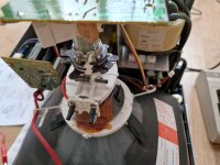
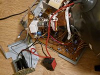
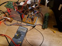
Unfortunately, this monitor is a major PITA to service. Apart from everything being glued with white stuff, it's impossible to have the chassis out with everything connected. The connectors on either side of the PSU or flyback are too short to have them on at the same time and the flyback assembly not bumping into the neckboard 😩

1801-5.jpg 1801-6.jpg

Have you guys taken apart one of these things? I thought it would be as easy as with a 1084...

WIsh me luck...
 
Alright, for future persons taking this thing apart:
The easiest way to work on this is to unscrew everything from the front part (power switch, LED and control panel), disconnect the degaussing coil and remove the zip ties. This allows to move the chassis out far enough to access everything needed without anything being too close to the neckboard. I had to put the flyback assembly back together because the leads were too short otherwise.

Continuing, the manual is complicated in regards of where you need to connect your multimeter leads to. It asks you to connect it to the leads of an electrolytic capacitor.. I found that it's easier to just find the nearest accessible exposed lead (disk capacitors, resistors etc.) on the schematic and hook up the multimeter there. Also, grounding that IC pin 31 made about 0.1 V difference.. I think this step can be skipped.. unless you have an idea why this would be needed

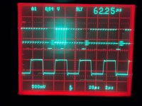
I verified on the scope that the signal coming from the C64 is 1 V pk-pk and proceeded with the measurement:
The result is that my B+ is too high, 116.3 V . The manual doesn't say anything about how to adjust it.

1801-7.jpg

The 'bleeding' effects on the checkerboard pattern are caused by a 'peaky' or uneven frequency response in the video amplifiers. Check that the video cable is good quality (Never use an ordinary audio lead) and that the monitor is providing the correct 75 ohm load to the video input line. Otherwise, it is a problem that will need to be tracked down internally. Are you using the ordinary composite input, or are you using the separate chroma/luma input?
The problem appears on both inputs and with different monitor cables. It must be something in the circuit. But before I investigate it further I would like to follow the alignment steps as described.
 
I had a quick look at the schematic. There is a trimpot (R554) called 'Tone' that appears to be a picture sharpness adjustment. You may need to tweak it to correct the peaky video response. For an unknown reason, the service manual does not describe how to adjust it.
 
Yep, I noticed it too when I was marking out the locations of the trimpots. I'll try it if the other adjustments don't help.

Anyone's Japanese good? I was looking at the datasheet of the VR (IC101 on the schematic, http://www.datasheetcatalog.net/de/datasheets_pdf/S/T/R/3/STR3115.shtml) and saw that it's 115V +/- .8 V, which would make 116.3 V out of spec.
How does this work? Input current in mA regulates output voltage? The sample diagram in the chart has a variable capacitor(?), but in the monitor's circuit there's no such thing. Would that make either the VR or one of those resistors and capacitors in front at fault? I'm not an expert with circuits...
 
I found the problem, but how do I solve it? The transformer's output voltage is 110 V on the white colored connector wires, at least according to the label on it. Since I live in a 230 V country, this makes it output 120 V. I turned down the isolation transformer's output voltage to 220 V which resulted in 115 V at the secondary (still too high but tolerable). It reached 110 V when the input voltage was 210 V.
At this value, the B+ was 115.2 V at no brightness and 114.5 V at full brightness (using the front panel controls). which would be within specification.
Suggestions?
None of the issues with your monitor's picture suggest that the line voltage being this way or that by 10 to 15% would have any effect at all.

All the TV's important circuitry is normally driven by regulated voltage, so the line voltage, and the transformer's output voltage can swing around quite a lot with little to no effect on the picture. Or did the faults disappear when you lowered the line voltage on the variac ?

All that happens when the transformer output is in the higher range, there will be more power dissipation in the voltage regulator circuits downstream from the transformer and rectifiers, but they are designed to tolerate that(in most cases). You should find as the schematic suggests there is 115V DC out of the voltage regulator IC, not affected by adjusting the variac, I would expect, over a range of around 200 to 240V line voltage. There in an unregulated 12V supply, that just appears to run the audio amp.
 
Last edited:
None of the issues with your monitor's picture suggest that the line voltage being this way or that by 10 to 15% would have any effect at all.
Correct
All the TV's important circuitry is normally driven by regulated voltage, so the line voltage, and the transformer's output voltage can swing around quite a lot with little to no effect on the picture. Or did the faults disappear when you lowered the line voltage on the variac ?
They did not disappear...
All that happens when the transformer output is in the higher range, there will be more power dissipation in the voltage regulator circuits downstream from the transformer and rectifiers, but they are designed to tolerate that(in most cases). You should find as the schematic suggests there is 115V DC out of the voltage regulator IC, not affected by adjusting the variac, I would expect, over a range of around 200 to 240V line voltage. There in an unregulated 12V supply, that just appears to run the audio amp.
But: I measured the output pins of the regulator and the B+ level moved by changing the voltages on the variable transformer as described in my post. I could probably leave it like this, but if it can be avoided and to extend the lifetime of the components I would like to do it. The heatsink does get really hot...

I believe this monitor was really meant for 220V and nothing else, suggested by the "power input" part of the manual, where it mentions two different transformer models, a 220 V and a 240 V one: https://archive.org/details/manual_1801_SM_COMMODORE_EN/page/n2/mode/1up

The audio circuit can be ignored I think, I just noticed that it gets really loud really quick as you turn the volume knob.

I'll continue with the adjustments, but it would be great to find a way to reduce the output of the VR a little.
 
Correct

They did not disappear...

But: I measured the output pins of the regulator and the B+ level moved by changing the voltages on the variable transformer as described in my post. I could probably leave it like this, but if it can be avoided and to extend the lifetime of the components I would like to do it. The heatsink does get really hot...

I believe this monitor was really meant for 220V and nothing else, suggested by the "power input" part of the manual, where it mentions two different transformer models, a 220 V and a 240 V one: https://archive.org/details/manual_1801_SM_COMMODORE_EN/page/n2/mode/1up

The audio circuit can be ignored I think, I just noticed that it gets really loud really quick as you turn the volume knob.

I'll continue with the adjustments, but it would be great to find a way to reduce the output of the VR a little.
That is odd, the regulator has failed if it is not regulating. Can you measure the DC input voltage to the regulator...

it should be well above 115VDC I would guess about 20 to 40v higher, it depends on the secondary (rms voltage x about 1.4).

If it is not regulating it might be overloaded/overheated if the current shunt resistor 300R 10W is defective, check that with the set turned off. And also check the resistor divider and filter capacitor that forms the IC's voltage reference and check the IC has good thermal bonding to the heat sink, before blaming the actual IC itself.

When you adjust the variac, does the size (height and width) of the image change ? It should do if the set's B+ is not stable.
 
Last edited:
The 10W shunt resistor measures 290 Ohms which seems fine. I'm a bit confused about how this regulator circuit is supposed to work. do I have to measure the components out of circuit? Some don't really read what they're supposed to be.. I dread desoldering stuff from this board because I have to take apart this metal frame and half of the connectors aren't real connectors, but seem to be crimped wires soldered to the board.

The picture changes very minimally when adjusting the input voltage (barely a millimeter), as much as a 1-2V variation on the B+ would do I assume. The IC is firmly bolted on to the heatsink, and it's not like there are swings in values after running for a while (the image is stable in general, it doesn't move or jitter on its own).

Anyway, here's the measurements (approx.):
Primary VAC inSecondary VAC outVDC IC101 Pin 1+2 inVDC IC101 Pin 3+4 out
~210~11024115.5
~220~11831116.5
~230~12438117

Btw, none of the trimpots influenced the "peaky" video signal. The tone control just made it sharper or blurrier. I could hook up a scope to the emitter of Q502 to check it, but I have to refresh my memory on the proper procedures on how to not kill my scope in a live circuit with more than 12V
 
With the input voltage varying 210 to 230V AC, and the output of the regulator varying 115.5 to 117V, that looks stable enough to me and the small amount of variation in picture size seems ok. Nothing I see with that looks like a problem.

Generally the tone pots would affect the high frequency edges corresponding to the sides of say a white vertical block with surrounding black. But any overshoots are more obvious on the black to white transition, because on the white to black, the effect is obscured by a cut-off CRT beam.

Assuming :
1) the source signal is good
2) you have a proper 75R cable
3) the cable is terminated into 75R at the VDU, then;

The blames lies in the VDU video processing circuit. It would be possible to see the effect quite easily on the scope across a single scanned line of the checkerboard pattern.
 
Ok, if the PSU is not problematic then I'll take it. It's not like this monitor is running everyday for several hours.
1) the source signal is good
2) you have a proper 75R cable
3) the cable is terminated into 75R at the VDU, then;

The blames lies in the VDU video processing circuit. It would be possible to see the effect quite easily on the scope across a single scanned line of the checkerboard pattern.
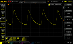
I have checked 1)+2) on the scope, it does display a 1 V pk-pk signal. 3) is also fine, at least the 75R resistor at the video input reads as such.
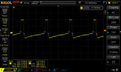
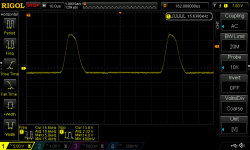
Where do I get one scanned line? You mean this?: 1801-q502.png

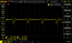
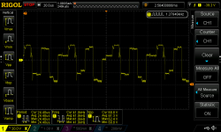
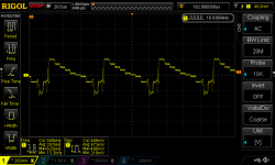
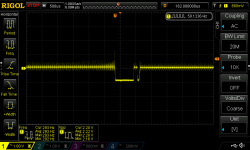
I also measured all the waveforms in the service manual p.23. Most are good, some are strange or I can't explain them (some are missing due to the 10 file limit, but those were good waveforms anyway)

Some remarks:
1801-8.jpg this is with the "Screen" control on the flyback turned down quite a bit. I found it curious that they're still so pronounced, even though the rest of the picture disappeared

1801-ic-pin10.png IC301 pin 10 reads more than double than what it's supposed to be (1,5 V pk-pk)

1801-ic-pin18.png IC301 pin 18 also doesn't look like in the manual, but at 50mV there could be some other noise from around

1801-q701.png The supposed to 40 V p-p also reads too high and looks different

Now that the video input looks fine, I've got even less of a clue what could be going on

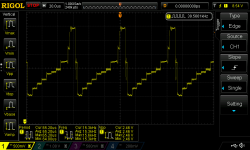
Edit: The square-wavy signals are the checkerboard pattern, the stairs is a colobar
 

Attachments

  • 1801-ic-pin27.png
    1801-ic-pin27.png
    41.2 KB · Views: 4
  • 1801-ic-pin16.png
    1801-ic-pin16.png
    43.7 KB · Views: 4
  • 1801-ic-pin5-colorbar.png
    1801-ic-pin5-colorbar.png
    41 KB · Views: 3
  • 1801-ic-pin4.png
    1801-ic-pin4.png
    39.2 KB · Views: 4
  • 1801-cn503-5.png
    1801-cn503-5.png
    44 KB · Views: 5
A line just means, as you guessed looking between two horizontal sync pulses. And if there is a checkerboard pattern and you will see a square wave during actual picture time, unless the scope has latched onto an H sync pulse around vertical blanking time, but it is normally easy to get one prior to a line of the checkerboard, simply connecting and disconnecting the signal or by switch back and forth between another sync source. (A scope like the Hitachi V-509, with a V sync separator built in, and a delay timebase, you can sync to the the V sync, and use the delay timebase to scroll along expand it out and inspect any horizontal line in an odd or even field and you can identify the fields too)

But, to see subtle defects in the waveform frequency response requires a few things;

The scope earthing is critical and it should be connected to the common point close to the circuit being measured, if it is not the recording will be corrupted , typically with high frequency interference from the H output stage. There is some sinusoidal high frequency interference riding on some of the recorded waveforms.

It also requires a perfectly compensated x10 probe and at least a 50 to 100MHz bandwidth scope. ( I always find digital scope recordings more difficult, but I think your scope is up to it, I normally use a Tek 2465B or a V-509 for TV work because it has sync seps built in)

The idea is to follow the checkerboard square wave from the video input & input circuits, all the way to the CRT, and see if you can find where the frequency response becomes peaked , or rings a little after the rising edge of the square signal waveform that corresponds to the checkerboard.

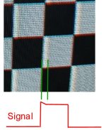
Just to clarify, the part of the image bothering you is that the leading edge of the checkerboard pattern, just after it goes from black to white, overshoots a little and is more bright on the left hand edge of the white block, picture attached...is that correct ?

Grey scales are not as good to find a frequency response problems, because there is less of a voltage step between voltage transitions and less ringing (overshoot) in any of the video amplifier stages.

Sometimes, some of the longer time frame smear effects on some VDU's have turned out not to be ringing effects at all, but abnormalities induced by aged electrolytic coupling caps in the video signal pathways. It would be interesting to turn up the screen brightness to make black look grey and see if there is a longer dark tail on the trailing edge (right hand side) of the white block.
 

Attachments

  • Signal.jpg
    Signal.jpg
    59.9 KB · Views: 6
Last edited:
Just to clarify, the part of the image bothering you is that the leading edge of the checkerboard pattern, just after it goes from black to white, overshoots a little and is more bright on the left hand edge of the white block, picture attached...is that correct ?

Grey scales are not as good to find a frequency response problems, because there is less of a voltage step between voltage transitions and less ringing (overshoot) in any of the video amplifier stages.
Yes, correct that's the "faulty" part (at least I dare to say faulty because it doesn't appear on other monitors).

Which pattern do you recommend for fault finding?
Sometimes, some of the longer time frame smear effects on some VDU's have turned out not to be ringing effects at all, but abnormalities induced by aged electrolytic coupling caps in the video signal pathways. It would be interesting to turn up the screen brightness to make black look grey and see if there is a longer dark tail on the trailing edge (right hand side) of the white block.
This is ineed the case and maybe you're onto something.

It seems you really like these two particular scopes... I'd say the same task could have been done on the DS1054z but since I have the Tek you mentioned (I just barely use it because it's loud and I'm too lazy to recap it) we might aswell fix it with period appropriate gear...

This is the signal from the C64 connected to the scope directly, displaying the checkerboard pattern:
1801-checkerboard.jpg
I probed the emitter of Q502 again and it looks almost identical, so I didn't take a pictre. There seems to be even slighly less overshoot when measured there.

Where can I measure to find the signal at a later or the latest stage before it goes to the CRT? I assume I'm looking for the waveform you drew in the attachment.
 
Excellent quality scope recording, that is the sort of thing I am used to. It does have a blacker than black overshoot which I did not draw on the diagram I posted as I was not sure if it was there.

When you connected the C64 signal directly to the scope, did you terminate it at the scope end with a 75R BNC terminating resistor (on an inline plug or a BNC type on a T fitting) with the scope input on high Z, or was the scope set to high Z on its own in or 50R input mode ?

Lets say the source signal still looks like that , connect into a 75R load, then it could be a combination of factors, in that the source signal may contain the overshoots, but the other VDU's you have tried don't display it because they have a lower overall HF response in the video circuits have rolled it off.

I will have a look at the schematic and work out the places along the way to test the signal in your VDU.

"Which pattern do you recommend for fault finding?"

Well for this particular issue the checkerboard because it shows up the overshoot issue well on a black to peak white and white to black transition. For other issues like scan linearity or doing convergence adjustments it is best to use the crosshatch pattern, but for convergence the Dot pattern works well too, and for other issues the greyscale and or color bars depending what the problem is.
 
Last edited:
Back
Top