• Please review our updated Terms and Rules here

Commodore C64 "Re-Brick" Power Supply

KevinO

Experienced Member
Joined
Apr 13, 2012
Messages
380
Location
Des Moines, IA USA
I've been working on this project for over a year, and I thought I'd like to share it. I thought I might sell a few on a limited basis, but mostly I wanted to see if it could be done.
P1050180.jpg

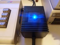
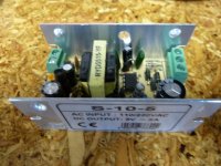
This is an original US Commodore 64 power supply, known as the "brick", and reviled by Commodore users the world over. What makes this different is that it's been gutted and replaced with new parts. I always wanted to try this, and about a year and a half ago I found a 5v 2a switcher that would fit. The switcher is made by Sure Electronics, but I can't find it on their website anymore, which may be an ominous sign. They're still on Ebay from various sellers. The switcher is adjustable, overvoltage protected, short-circuit protected (it shuts down until the short is removed) and fused.

Here's the switcher:
P1050148.jpg

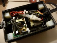
Oh, and here's the insides of what I'm calling the "Re-Brick".
P1050181.jpg

The 9VAC section is a simple wall-wart type transformer, removed from the plastic case and epoxied into the C64 brick case. I've got the 9vac fused at 3a, which seems high, but that's actually what I found in a couple of stock PSs that I took apart.

I wanted it to look like the original C64 brick, but give a hint that it's not stock, so I took the LED that's built onto the switcher and brought it out to the case. I think it looks awesome this way. I built 8 of them total, and three of us tested them thoroughly for a year with no problems. So I decided it would be safe to sell a few at ECCC in Chicago. That's when my education about switcher noise began. We found that on some machines we can see interference patterns running up the screen. This happened on a late model VIC-20, and it seems to happen on any C64 where you use an S-Video adapter cable. I get NO noise on any of my 3 breadbin C64's, either on my 1084, 1701, or when connected via RF on my Samsung LCD TV.

So I still consider it a success, but I've been working on trying to get the noise out, which is a harder task than I thought it would be! Clearly, this is not a replacement for Ray Carlsen's awesome new PS, and we're all holding our collective breath to see what comes out of Jim Brain and Bil Herd's efforts. Also, since my switcher only puts out 2A, it wouldn't be good for a Commodore REU or other power hungry peripheral. I use it with the uIEC all the time though!
 
Last edited:
That looks like you have put a lot of effort it KevinO and it looks well.

The only thing I would have done differently would be a fuse holder similar to the beige wedge supply and mount it in a similar way to the wedge.

Have you earthed the switcher and the transformer?
 
That looks like you have put a lot of effort it KevinO and it looks well.

The only thing I would have done differently would be a fuse holder similar to the beige wedge supply and mount it in a similar way to the wedge.

Have you earthed the switcher and the transformer?

Thanks for your input, it is appreciated.

I thought about an external fuse holder, but I had two problems with this. One, when I looked at them, they seemed to cost nearly as much as the switcher. Second, the unit wouldn't look stock. Having said that, the blinding blue LED sort of kills the stock look, doesn't it? The switcher is fused on the AC side. Unfortunately, the fuse is soldered to the board, so changing it would require removing the PS. There also is no fuse on the AC side of the 9VAC transformer, so using an external fuse would be good for that.

The switcher actually has a separate earth ground pin, so that's convenient. The transformer is only 2 pins, so no way to ground that, to my knowledge.
 
My previous post is in moderation limbo, maybe because I quoted Robert's link? Anyway, I thought again about Pet Rescue's comment about an external fuse. I think I had been on Digikey when I looked last time, and I swear those kind of fuse holders were coming up at $5 each, but I just looked at Jameco, and they have them for as low as $.95 each! That might be something worth considering, especially for safety considerations. I'm reasonably confident of my abilities, but it IS a homebrew solution after all, and if a short happened, it could be ugly.

I'm also interested in any input on the switcher noise. I'd be happy to show scope readouts if anyone is interested in that sort of thing. I'm getting an average of 200mv p-p of 100khz ripple, with some random harmonics (if that's the correct word) thrown in. The stuff is amazingly difficult to eradicate. The best luck I have had is using a salvaged dual-wound torroid from a C64, that filters both sides of the 5v line. That brings the ripple down to a much more reasonable 50mv p-p, which is the magical 1% margin that I would expect in the first place. Interestingly, however, it still doesn't eliminate the screen bars when I hook the C64 up to an LCD TV with an S-Video cable. A friend of mine suggested that my S-Video cable wasn't wired properly, or should have a capacitor in it somewhere. I didn't wire it myself, I think it's a BasicWayne model.
 
You could try re routing the 5v and 9v lines away from the top of the switched supply to more behind the aliuminium shield as I noticed they go over the top therefore prime to pick up stray RF.

I don't know if it would improve by fully shielding the switched supply too a bit like how modulators are shielded, my laptop supply inside the plastic case is fully shielded.

Also a lot of talk of filters but I'm not that knowledgeable on filters sorry.

I think fully shielding is a great idea. In fact, that switcher comes with a top cover that I've been leaving off. The edges of the holes where you have to bring the wires out are somewhat sharp, so I was worried about having a short, and I started leaving the top shield off. I'm going to remedy that and start putting it back on. Having said that, when I did that, there was no discernible difference in the noise on the 5v line. I should test it spread out on the bench and see if there's any difference.

I'm not an expert on filters either, but a common filter design is to have a capacitor across the DC output, then a coil in series, then another capacitor across the output on the other side of the coil. Oddly, this combination seems to make the noise worse rather than better, especially the higher frequency noise. Ray Carlsen suggested I put a 50pf capacitor across the output rectifier, and that didn't seem to have any effect either.
 
Progress! I finally got a chance to get back to this. I found these 3-lead EFI filters and it's getting rid of about 75% of the noise.

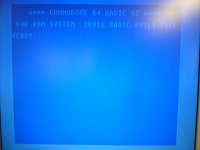
Here's a screenshot of the noise with the original PS, no filtering. There are two bands that roll up the screen quickly:

ScreenNoise-NoFilter.jpg

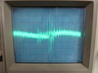
Here's what it looks like on the scope. 50mv range. The large spike is at 200KHz, which appears to be the switcher frequency.

ScreenNoise-NoFilter-Scope.jpg


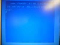
Ok, now here's what it looks like with the EFI filter installed across the +5v line. Actually it's in series with the ground lead going to earth ground:

ScreenNoise-WithFilter.jpg

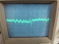
Here's THAT on the scope. See that the 200KHz spike is mostly gone. There's a lot of smaller stuff in the MHz range, but it doesn't seem to have any affect on the operation of the C64:

ScreenNoise-WithFilter-Scope.jpg

I think I'm onto something here! It's not gone completely, and the picture makes it look a little better than it is. If you look carefully on the right side about 3/4 of the way down, you can still see it, but it's much better. The manufacturer makes one that's higher capacitance. I'm going to try that one and see if I can get rid of it completely. Oh, and no voltage drop! W00t!
 
UPDATE: It occurred to me that I never came back and updated this thread! Life gets busy, and it's sad that we can't "retrocompute" all the time. So...I was able to get the noise reduced on the scope, but not on the screen! If anyone used an S-Video cable it was still noisy, and we had a couple of wierd examples of random SID noise. So I ended up scrapping that switcher altogether. I went to a Mean Well EPS-5-15, which is more expensive, but has virtually NO noise, and it's 3A instead of 2A on the original one. We've tested it with REUs and even SuperCPU and it works perfectly. Oh, and no visible bars on the screen using any kind of connection I've tested so far. Been doing these new ones for about a year and a half now, and they're solid.

Unfortunately, this project is time-consuming, and requires good old PS cases to work. So if you've got a box full of them, don't throw them out! I can use them. They're almost too expensive to ship though with all that epoxy weighing them down.

I'm making less than 10 of these a year, so don't hold your breath for a massive production run. I did take Pet Rescue's advice and we now have an external fuseholder! The new PS is an open PCB, and I was more concerned about safety on this one, so it became a necessary addition.
 
Wow this is really cool. I think I have a few of the old bricks. How do you get them opened, epoxy removed and still look good?
 
Some of the potting materials used in some devices are soluable in kerosene or diesel. I don't know if that is the case with the C-64 brick though.
 
Wow, great video that is exactly what I wanted to see. Way cool. I am going to have to go dig my file folder box full of Black and Beige bricks out of storage. Thanks!

This is being said many times but it was really silly of Commodore to fill these things with epoxy.
 
It actually made sense--the epoxy distributes the heat and the case becomes an effective heat radiator. One of the reasons that these "brick" PSUs fail is that they tend to "cook" themselves.
 
Better epoxy than some of the strange potting compounds I've run across in prewar radios. I don't think C= power supplies ever leaked any brown goo that dissolved plastic or dug a crater in finished wood.

One thing to always keep in mind with electronics from the C= era, and especially from C=, is that no one had any expectation of them still being around today, let alone anyone working on them.
 
Last edited:
It actually made sense--the epoxy distributes the heat and the case becomes an effective heat radiator.
The epoxy keeps in the heat, and the case is an ineffective heat radiator. If not mentioned before, the epoxy was CBM's way of preventing a p.s. fire; since oxygen is excluded, there can't be a flame.
One of the reasons that these "brick" PSUs fail is that they tend to "cook" themselves.
Right.

Just found a repairable C64 p.s... must install modern components,
Robert Bernardo
Fresno Commodore User Group
http://www.dickestel.com/fcug.htm
 
Back
Top