• Please review our updated Terms and Rules here

Commodore CBM 8032 video display problem

Actually Kevin, for me I think it may be learning "curb"... I feel like I'm still in the gutter! :)

Ok, so I'm going to stage 2.

1) Remove and socket the 4 x video RAMs (2114) with known working vic 20 chips (ma poor vic :-( "taking one for the team")
2) Re-seat UA3 (video gen)
3) Turn back on and hope for a greeting...

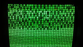
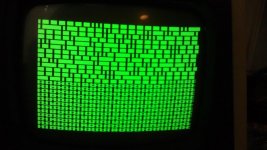
Dave, I've added a few more pics re; garbaged screen. First one is with UA3 (char' gen) chip in, second UA4 chip removed. Does this tell you anything?

Added a picture of the board, not that you'd see anything obliviously wrong with it...

Getting outa the gutter and onto the "curve" :)Board.jpgCharacter chip in.jpgCharacter chip out.jpg
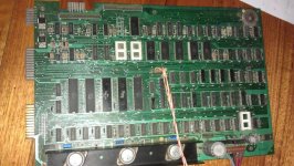
 
Dave, I've added a few more pics re; garbaged screen. First one is with UA3 (char' gen) chip in, second UA4 chip removed. Does this tell you anything?

With the character ROM (UA3) in, I see an "!" in the space between characters. This is not correct and may point to a bad UA3.

UA4 chip removed?? Do you mean UA3 or the UC4 RAM chip?? Either way the display looks very strange.
 
With the character ROM (UA3) in, I see an "!" in the space between characters. This is not correct and may point to a bad UA3.
Don't forget that alternate characters are in different video RAM chips, so the !s are all in the even chips (but not everywhere, and apparently in both low and high chips)

UA4 chip removed?? Do you mean UA3 or the UC4 RAM chip?? Either way the display looks very strange.
Indeed!

Just to confirm, did you (Jules) mean UA3 instead of UA4? I.e. are the two screens identical, fresh from reset, with the CG chip in and out?
 
Sorry Dave, I meant UA3 (character gen chip) not UA4 (which is hard wired).

I just tried my other 8032's char gen chip in UA3, exactly the same image...

I think the image with UA3 chip out is interesting as there's a distinctive difference from the top half vs bottom half (as also is the case with the chip in). Any clues with that? What part of the circuitry is responsible for the top half/ bottom half screen image? Possibly the 2114s?

Feel like a real detective now...
I think you're chasing a lot of red herrings; since the system is essentially working (beeps, reads KB etc.) the RAM, voltages, etc. are probably fine. Replace the 2114s as suggested in post #5 and let's take it from there; note that even without the CG you're still reading the reverse video bit from the RAM.

The 4 RAMs are arranged as odd and even characters, low and high 4 bits, so the upper/lower screen are upper and lower halves of the same chips.
 
Sorry you're parting out your VIC-20, but I understand when you've got the fever to figure something out.

Thanks for posting those excellent pics. I pulled UA3 in both my 4016 and 8032, and got fat unbroken bars across the screen. I'm guessing 25 of them, but I didn't count at the time. So that's definitely not what you should see. Can't wait to see what happens when you replace those 2114s. Barring any more severe weather, I won't be checking at 3AM though!

This is almost as exciting as working on mine! Good luck!
 
Thx guys!

Got all my sockets and a heap of extra tools etc... Initially I regretted not buying a working 8032 for a 'little' extra, but I think the journey so far has taught me heaps. And it's been great sharing it with you guys. If it all works out it will make my 8032 even that more special!

I'll update you after reseating the 2114s.

BTW, does the C64 have 2114s? Got an old one in the shed.
 
No, the C64 has DRAM rather than SRAM. I've learned it was one of the key points why the C64 was possible to pull off at all, the switch to DRAM at a point in time when it was getting cheaper.
 
UPDATE 1932pm Aussie time.

Lot's of great progress guys! But not quite there yet...

I've replaced/socketed all the 2114s and definitely made great progress (RIP Vic 20 :-( )

But as with all vintage computer repairs (so I've learned), there's usually more than just one issue.

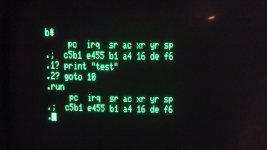
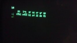
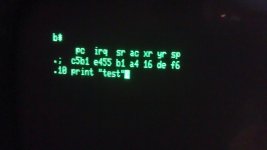
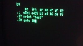
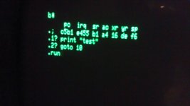
As you can see by the pics (first pic should be last... not sure how to order them on this forum yet), the startup screen has recognisable characters, but obvioulsy making no sense at all. I can type lines in and they come out as typed but when I hit return after each line, I get a "?" substitution for "0". I tried a simple program and it just goes back to the startup screen garble (it's been years since I've written basic, but I presume my program would fill the screen with "test")

I haven't started looking into this issue yet, but I'm thinking it should be a little easier to work at... although all good stories usually have a dramatic ending!

I've swapped over the GC chips, no difference. Double checked the UA3 solder joints, looking OK. Swapped over the 6502, no change.

Any suggestions??? (really happy with how it's progressing!)

5.jpg1 start up.jpg2.jpg3.jpg4.jpg
 
Well video is fixed, and now you are being dumped into the ml monitor. Great progress is right!

I don't know the answer to this one, could be either ram (system not video) or rom.

Later,
dabone
 
Ok, this is getting really interesting... I googled the letters on the start up screen "pc irq sr ac xr..." and apparently I'm in the sys 1024 "machine language monitor"!

http://www.atariarchives.org/mlb/appendix_f.php

What appeared to be random gibberish is actual machine language hieroglyphics.

Just gotta figure out how to fix it (hardware vs programming command).

Much more exciting than the Bluray I rented tonight!!
 
Def in TIM (machine language monitor) mode, although it doesn't respond to Commodore's machine language commands.

Andre Fachet's article on repairing pets states;

"Monitor after reset: When the PET comes up with the built-in monitor (TIM) instead of the BASIC prompt, check the value of the stack pointer. If it is very low (e.g. "01") then there is a stack overflow, probably caused by too many interrupts. Check the "VDRIVE" signal on the keyboard PIA or VIA IC. If it shows the vertical sync video signal, only that it is not between 0V and 5V, but between around 0V and 1V, then the VIA may be broken and pulling the signal low, so that the PIA has problems detecting the interrupt. "

I'm thinking this may be the issue.

Can anyone tell me how to test what he's talking about? (eg "...value of the stack pointer" "VDRIVE signal on the keyboard PIA or VIA IC" etc?
 
+4.6 volts pin 18 UB 12 dabone. Not good a schematics, but does that mean there's an issue?

Sorry, just read if it's between 1v and 5v all's OK.

Done lots of googling.. it's late... still no answer.

Def can't rectify it with commands so it must be a RAM/ROM issue???

Where do you recommend I start with this one guys? Piggyback technique? There's a heck of a lot of RAM/ROM chips... If someone could let me know the locations of the RAMs/ROMs I should test (eg is it the UAs?, UBs? etc) that would be a great start.

Think I might call it a night, start fresh tomoz :)
 
The stack pointer is okay, it shows SP=$F6, that's not an outrageous value, so Andre Fachat's tip doesn't apply here.

Somewhere during the startup sequence the 6502 encounters a BRK instruction ($00) that starts the Machine Language Monitor. Since apparently the Kernal and the editor are working (at least the parts that read keyboard input and print text on screen), I'd say the main suspect is the BASIC ROM, or the chip-select circuitry associated with it.

The good news is that now you have TIM, you can easily dump the ROM areas to screen and compare the output to known values. To start with, you can check if any of the ROM areas is showing only zeroes.

EDIT: Silly me, the MLM SHOWS you where the BRK is...: $C5B1 (the number under "PC"). According to these schematics, that's UD9. That's the high BASIC ROM.

You should be almost done!

===Jac
 
Last edited:
Wow, thx Jac. Sounds like, literally, the answer is straight in front of me! Good call.

So, in "I'm not really great with electronic" terms, does that mean UD9 is the culprit? Do you suggest I just replace UD9? Not sure if I need to now, but how would I "dump the ROM areas to screen and compare the output to known values" (BTW- as much as I'm in the machine language monitor, I can't get it to respond to any MCM commands).

Thx, Jules.
 
Hm, does the "m" command work to get a memory dump in hexadecimal? Ideally though you would want to dump the ROM content directly to a storage media for some sort of comparison. I quoted the TIM chapter from the CBM-II manual, but since that one is "extended version" I don't know how much applies to the one in a 8032.
http://www.commodore128.org/index.php?topic=3463.0

But yes, if you have a ROM replacement or at least being able to burn a 2532 you might find yourself close to finishing this one.
 
EDIT: Silly me, the MLM SHOWS you where the BRK is...: $C5B1 (the number under "PC"). According to these schematics, that's UD9. That's the high BASIC ROM.
Jac,
That is a good theory but what about the D000 ROM? The startup code goes from the F000 rom to the E000 ROM where the screen is initialized, and then the D000 ROM (UD8 ) for the setting of the stack pointer, RAM memory test, screen clearing and the Commodore welcome screen. We are not getting too far in this process when we apparently wonder off and hit a break instruction in the B000 area. If the monitor is working, which is in the D000 ROM we may find more information. But if the monitor is not working, we may suspect the D000 ROM. This is quite a fun problem.
-Dave
 
Back
Top