• Please review our updated Terms and Rules here

Commodore PET 2001 (with pictures) Questions about the mods

SkyCaptain

Experienced Member
Joined
Apr 18, 2020
Messages
85
Location
Basel-Stadt, Switzerland
Hey guys, im back with an other PET i found on my quest to find an affordable but working PET.

So the machine is pretty amazing with many added boards, it came with a printer and a dual disk drive.

On first glance, it looks like one of the 2001 with the full sized key board and green screen, but upon further inspection I realized that the screen just had a green foil over it, and that the keyboard was a conversion. The Screen was actually white and on the inside, there was still the frame for the tape drive. So im pretty happy about that, it seems like this is a very old machine. One step closer to my dream PET.

Sadly the after market keyboard is the problem, i think its the ribbon cable. Its a very cheap one it seems, paper on one side and clear foil on the other. The glue holding them together is not sticky anymore, and the cables move around and are probable touching each other when i close the case.

It has some nice features on with these switches and buttons. Apart from the common reset there is a screen colour inverter button.

As i said, there are a few boards in there that i dont know what exactly they do. One, the previous owner said, was the printer board.

One thing i did do while cleaning the machine was to replace the 6502 with the Tynemouth ROM/RAM replacement board that i have from the other PET repair (that is still going on and im kinda ashamed that its now been a year, but updates to that thread will come too). That worked pretty well and I was able to switch through all the modes.

So yeah, here are some picture, and i would really appreciate some input un what these addons could be. Specially the one that raises the 6502 like that...

Thanks a lot!!
Skycaptain
 
I am pretty confident that the little PCB on the rear right (with two EPROMS) is a switchable character generator.

The top board looks like a 64K RAM board (I assume the RAM devices are 4116 - 16Kx1). Not sure what the ZIF socket is though - or what is plugged into it. Does this card have any markings on it at all - it looks like a commercial PCB - as opposed to the other 'homemade' ones.

The ROMs have clearly been moved from the main logic board to a daughter board. My guess is these were an 'aftermarket' BASIC upgrade from the original 'buggy' BASIC 1 to something else. From the photograph you don't have the '***' version but the upgraded '###' - but not quite BASIC 4. I wonder if they took the opportunity to make the sockets EPROM computable at the same time - so they could perform the upgrade themselves?

Not sure what the PIA (guess) is on the ROM board - unless it repacks a PIA on the PET board and is some form of bank switching arrangement for use with the RAM board. I am guessing here.

I suspect the smaller PCB (with basic TTL chips) may be the 'glue' logic to support all of these modifications?

Looks an interesting project you have there!

I do like the keycaps though. The ribbon cable may be 'poor' but the keyboard quality itself looks very good!

Dave
 
Hi Daver2

You are right about the character switcher, It has the Original Character set, and one with the German Umlaut "ö" "ä" "ü".

The 64K ram board, i dont know if they are 4116, they say MOSTEK 7842 and MK4115P-40 on them. The only marking i found on the board itself was "EXPANDAMCM". the C could be a "e", its a bit corroded, but since every other letter is caps i doubt it.

PIA on the ROM board? if i take it correctly, this is not the PIA, but the 6502 processor raised up. The PIA 1 and PIA 2, at least according to an "Commodore PET 2001-8 motherboard" picture on google, are still where they belong. I removed that whole daughter board and put the Tynemouth ROM/RAM replacement board in that socket. I honestly would have loved to plug it into the daughter board itself but then the RAM board wouldnt have fit on top.

The smaller one with the basic TTL? the one right next to the PIA, over the red LED?

I have repaired the keyboard cables and the keyboard itself really is very nice.

So i have been sent a hand full of documents by the previous owner which he found, among them is a "DISKMON USER'S GUIDE". Does this help maybe further identify these boards?

Im just going to think out loud here from reading the guide briefly. I need the daughter board with the 6502 and the ROM's on it, because the ROMs there for the DISKMON operating system. Which needs a disk too as from with i can gather. i will see if i have that too.

Sooo... Remove the Tynemouth ROM/RAM replacement, put back the original, and find out how and what DISKMON exactly is. It does seem to operate not just the dual disk drive that i got, but also the Epson printer.
I wonder if I could just take the ROM chips from the daughter board and put them back into the original socket on the main board, and then use the Tynemouth Board to replace just the RAM. Or do I even need that if im going to be able the access the 64K RAM from the EXPANDAMEM card.

many many questions hahaha

Thanks
SkyCaptian

EDIT: I just found out that EXPANDAMEM is an extension board by the same company that made DISKMON. so thats something
 
Last edited:
The MOSTEK MK4115P-40 is an 8Kx1 DRAM. As a consequence, a fully populated card with these devices would be 32K. 7842 is the date code of manufacture - week 42 of 1978.

I see ROMs are fitted.

PIA / 6502 - close!

If my memory serves me correctly (and I may be wrong here) CompuThink had a DISKMON program - but they also had a separate disk controller that appears to be missing from your machine. As a result, DISKMON may not do anything for you. I will have a hunt around to confirm/deny my statement...

You got the dual disk drive then? I wonder if I have missed the disk controller somewhere in your photographs?

In order to work out if you could put the EPROMS into the main PET board you will have to identify exactly which make and product code (a) your PET mainboard is and (b) the EPROMS are.

Dave
 
I will post more pictures today/tomorrow

Yes, I have the dual Disk drive too. So could it be that the DISKMON card works in conjunction with the EXPANDAMEM expansion card? I have a total of 3 cards plugged into the EXPANDAMEM card, and one of them looks like an Apple II disk card. (I have 2 apple II Europlus with disk drives. thats why i know how these look like or.. that they look similar)

it seems to me that this is a relatively rare and at the time expensive modification. I think i will do best by putting everything back to how it was. Not every day you see a fully decked out PET like this.

Thanks
SkyCaptain
 
Ah, I didn’t see photograph 7 to start with. Yes, that looks like a disk controller. Does it have a 40 pin disk controller chip on it?

The ‘logic board’ I was referring to is the one running from left to right in photograph 11.

Looks like you have an interesting ‘find’ there - and it looks fairly complete (if you can get it running).

Dave
 
Ive added a few more pictures under the link!

So yesterday, disaster struck. I out everything back together and tried to turn on the whole thing. As per manual, PET first, then printer, lastly the disk drive. Disk drives started to spin up and then i heard a "pfff" kind of sound and smoke started to come out of the box.

So i have taken the disk drive apart and found the fault. there are pictures of that too. I guess now i have to find a schematic for this, which is probably not going to be easy, find the part that broke and try to replace it.
Im not really sure what this means for any components up or down the line of this part.

anyways, ill post more news when available.

Thanks
SkyCaptain
 
Hmmm,

Either it has been overvoltaged or the voltage has been applied the wrong way round.

What manufacturer, make and model is the faulty disk drive? There is a fair amount of data available online for disk drives.

It is interesting that a lot of boards for your machine have been ‘home built’. I wonder what the history of this machine was?

Dave
 
Supplied the wrong way around cant really be, right? I cant plug in the power cable the wrong way on either end, and its not like the ribbon cable carries any power, just data. Because the ribbon cable is the only one that I can plug in either way as it is missing the notch on one side that would correspond to with the socket on the back of the device.

So over voltage? Some voltage regulator broken?

I have found the manufacturer of the drive, Its Pertec, and i think the drive is either the FD200 or FD250. I have found a manual with schematics too. So im gonna see what part this should be.

As for the history of the machine, I dont know much about the 1st owner, but the 2nd one was a teacher, he got the machine around 1980 and has had all these upgrades done to it.

Thanks!
SkyCaptain
 
So i think i have the right part
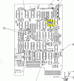
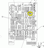
It looks like on the board, this part here is broken:

: Click image for larger version  Name:	Broken part.gif Views:	0 Size:	70.6 KB ID:	1211210

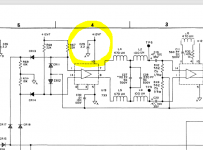
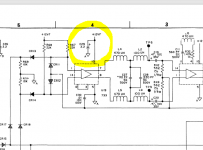
Which, in the schematics looks to be this part here:

Click image for larger version  Name:	C29_location.PNG Views:	0 Size:	68.3 KB ID:	1211211

Now... what does this mean? i was expect a little more information from the drawings. Because im not entirely sure where to go from here.

Thanks!
SkyCaptain!

Edit: No, wait, i think i need a Polarized Capacitator with 2.2uF? im gonna keep looking but i think im getting somewhere haha.
 

Attachments

  • Broken part.gif
    Broken part.gif
    70.6 KB · Views: 1
  • photo61664.png
    photo61664.png
    68.3 KB · Views: 1
Last edited:
Ah, it's a capacitor. I assumed it was a diode of some kind... Wrong assumption on my part.

That would be a tantalum capacitor then and (yes) they are prone to go bang with age...

However, it would still be a wise precaution to measure the +12V rail with a multimeter.

The disk drives on my Cromemco Z2 have their own voltage regulator boards. I disconnected the regulator boards and tested them on the bench (with a small load resistor) and one of the +12V regulators had gone short circuit. If I had have just powered up everything - I could have damaged one of the disk drives in the process.

Dave
 
Daver2, "The disk drives on my Cromemco Z2" wow thats a really cool machine, never even heard of them. But just to confirm i dont do anything stupid, would you disconnect the second drive from the power supply too? then flip the switch and check if the power supply actually delivers the +12V? Im a bit scared of just turning it on again even with the broken drive removed from the case.


Hi Dwight, thanks for the confirmation. I have here a filtered selection through my parts supplier, is this correct?
Axial 2.2 uF 25 VDC Tantalum Capacitors - Solid Leaded – Mouser Switzerland

Thanks!
SkyCaptain
 
Yes, the Z2 gives you a hernia if you try and move it... Inbuilt anti-theft device...

Yes, I would disconnect all of the drives etc. and measure the dc voltage with the drives disconnected.

If the disk drives have their own voltage regulators - they generally don't like to be run unloaded. An LED and a series 1k Ohm resistor connected between the +12V and 0V lines should be enough to keep the regulator happy. If you measure +12V (of the correct polarity) you should be good-to-go. Don't forget there will be a +5V power rail as well.

Yep, that part looks OK. Just check the data sheet and measure the physical dimensions of the bits you have left to make sure it will fit.

Dave
 
one day I will want something like that too. But for now it is too niche, and my knowledge of the inner workings of a computer too limited to enjoy having such a device.

"they generally don't like to be run unloaded. An LED and a series 1k Ohm resistor connected between the +12V and 0V lines should be enough to keep the regulator happy."
I dont fully understand this part yet, but ill be home in a hour to reread your comment with the device in front of me. This often helps clarifying things!

Thanks again!
SkyCaptain
 
Alright, so the two cables coming from the PSU to the disk drives are 4 wires each. so I have red, black, black and blue. On disk drive 1, i get 5V, 5V and -12V. One Disk drive 2 (the one that broke) i get 5V, 5V, and -7.80V. So thats already a bid difference.

Im not entirely sure why im getting negative 12V and not positive. You did say I needed the correct polarity, which it doesnt seem i have.

Thank You
SkyCaptain
 
The two black wires should be 0V, so connect the negative (black) probe of your multimeter onto one if these. These should be the two inner pins of the floppy power connector.

With the positive (red) probe of your multimeter read the dc voltage on the red and blue leads. The lead connected to pin 1 of the floppy power connector should be +12V and that on pin 4 should be +5V.

It is possible you had the multimeter leads around the wrong way when you measured the +12V rail?

The manual states that the power supplies should be +5V and +12V (definitely not -12V).

I would like you to to retake the measurements again before I suggest anything further.

Of course, don’t have the disk drives connected when you power up!

Dave
 
OK, so we know the power supplies are good and the most likely scenario was that the capacitor just committed suicide rather than being murdered!

I guess your strange 7V or so was measuring between +5V and +12V? That’s why I wanted to double-check how you were measuring the voltages...

Go for it when you have replaced the dead capacitor. However, I would first power up the drives (a) one at a time and (b) without the signal cables being connected.

I know it takes longer, but following a logical sequence (and noting down what you do at each step and what the results are at each stage) means that we can identify at which point things went awry.

Before connecting up the drive signal cable, we need to make sure which way round it should be first... Identifying how it should be connected first can avoid problems down the line.

Dave
 
Alright, im going to order the capacitor then.

considering this just happened, is it maybe wise to make note of most/all of these capacitors and order a bunch of them for the event this happening again in the near future?

Thank You
SkyCaptain
 
Back
Top