• Please review our updated Terms and Rules here

Commodore PET 4008 with strange issues?

BowmakerFox

Member
Joined
Mar 7, 2024
Messages
16
Greetings all,

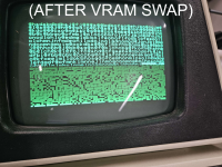
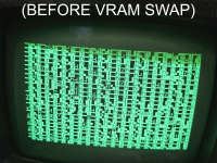
I'm new here, but thought this might be the right place to ask for any kind advice in fixing a PET I acquired recently. I've attached several images of what occurs on boot having cleaned the board and sockets to hell and back.

I suspected initially that the issue was VRAM, so I swapped the original MOS MPS 2114s for two NEC UPD2114LO-2s that I've used with no issues in several C64s. As attached, the weird garbled mess on the screen is different, and swapping the new VRAMs around seems to change which characters are in what position; otherwise (without swapping positions), they are the same on every boot.

There's no familiar beep / chime when switched on, and having removed the 6502 seems to have absolutely no effect on what's displayed.
I've also checked the voltages on each power line and they correspond to the diagrams, give or take ~10%. The traces all seem visually spotless too.

Don't suppose anyone has any advice on what could be at fault, or what to check (and how, I am a little dim).
Thanks again!
 

Attachments

  • afterVRAM.png
    afterVRAM.png
    1.3 MB · Views: 17
  • beforeVRAM.png
    beforeVRAM.png
    1.5 MB · Views: 17
Update:
If it's of any relevance, the crystal oscillator was faulty; the frequency input on the 6502 was all over the place. Having replaced it, it's now a solid 1MHz, as are both output frequencies on the chip. I swapped back to the original VRAM and have concluded that the difference in garbled characters doesn't mean anything, and that it's actually just what was last in it given that it's static.

I've checked the 6502's sync pin and it did *-something-* on boot (similar looking waveform to the clock pulse, except didn't last long).
I now reason based on the Zimmers schematics that the 4008 doesn't have a chirp on boot (unfortunately!), at least as far as I know, so I can't use that to troubleshoot.

I'm edging on replacing all of the stock RAM ICs (thankfully not a board with the punched-out RAM slots) but because of the associated cost I'm hoping someone here might be able to offer a second opinion first.
Cheers
 
Last edited:
The best bet is to get Daver2's PETTEST ROM and it will significantly help testing.

What tools do you have for diagnostics ? A scope would be useful

A No Op board is really useful tool as it allows easy checks of the memory decoding logic which does throw up problems on these machines.
 
First of all, as these are your first posts, welcome to VCFED where we try our best to look after your PETs...

You will be under moderation for the first 10 posts - so your posts will take a short period of time to appear.

Do what Gary says...

If you can't find my PETTESTER code and documentation, I can point you at it.

Knowing what test equipment you have access to, and what experience you have repairing electronics and understanding schematics etc. will help us pitch our advice at the correct level for you.

Dave
 
Hello and welcome, here you will surely find very experienced people who will help you solve the problem. They've helped me many, many times, right Dave? ;) Ask Dave where you can download the Pettester bin file (provided you have the ability to burn EPROMs).
Do you currently have EPROMs or original ROMs installed?
 
Hi folks, sorry for the late reply.
To answer your questions:

1, I have a scope, meter and soldering/desoldering equipment.
2, I started out repairing 64s. I've only just moved to the level of fixing a PET, but don't find schematics too daunting though I'm definitely not an expert.
3, I don't have an EPROM burner and while I could get one I'm reluctant to; don't have much monetary throughput if you get my drift. I did find some old 27XX EPROMs of different capacities in the workshop where I work, but I understand they're not natively compatible with the PETs. With that in mind, it is running the original ROMs for now.

I can get some EPROMs and a burner next payday if it comes to it, if that seems to be the general consensus - any recommendations as to which EPROMs and programming equipment to look for would be greatly appreciated.

While I'm at it, I may well replace the 4008 RAM ICs anyway - not sure 8k is going to be enough for my needs later on, and having not had my expansion sockets punched out makes me think I have a bit of a requirement to otherwise I'm taking that I can for granted!

But yeah, any suggestions as to starting with EPROMS would go a long way, thanks again
 
The question regarding the ROMs are which ones are in IC sockets and which ones are soldered in?

Dave
 
Ah, I see.
I've attached an image of the larger IC section of the board so you can see what I'm seeing. Most of them are socket-ed fortunately (if I'm correct, all).

The RAM replacement / upgrade ICs arrived a tad earlier than I expected so I might've jumped the gun and swapped all of the TMS4108 out for TMS4116 ICs in new sockets - I haven't changed the shunts so to my understanding it ought to still act as an 8k model (didn't want to add potential points of failure). Alas, this didn't solve the problem.

(In the image, I'd taken the board out of the machine hence the missing keyboard connection)

Hope this helps

IMG_20240404_232643.jpg
 
Given the above socketed ROMs, do you think it best still to look to getting some EPROM hardware or are there any other things I ought check first?
Regards
 
The first thing is the white IC sockets.

They are notoriously bad for making poor contact with the IC pins.

Dave
In that case I'll de-ox the lot of them and continuity test them tomorrow to make sure that isn't the issue. If needs be I can replace the sockets.
I'll get back to you and see if any are dodgy.
 
The first thing is the white IC sockets.

They are notoriously bad for making poor contact with the IC pins.

Dave
Sorry for the massively belated response, been wildly busy at work...
I just tested the continuity of the pins on every socketed IC, two of them seemed to have the odd pin that doesn't make proper contact, so I'll see if I have enough sockets to replace them and will let you know if it makes any difference
 
I just did the above, and found two sockets which weren't making dependable continuity and I didn't trust them. I replaced both sockets, alas breaking a trace in the process (I have since run a jump wire as best as I can)
Now that the 901465 and 901447 are making proper contact, I fired it up and wow, it's definitely doing... something... new.

On boot, it now shows the same kind of garbled rubbish as before, but about a second later it clears and displays something else of little meaning. As usual, no response to keyboard inputs or anything.

To my knowledge, a PET should display a garbled mess then clear, so I'm hoping this is a step in the right direction.
I believe I've attached an image of the screen it displays after clearing, and hopefully a video of it doing so.

IMG_20240413_001108.jpg


Cheers
 
Correct.

You should get random characters displayed until the CPU exits from reset. Then the screen should be cleared and BASIC initialised.

Now what we need is a copy of my PETTESTER installing so we can see what is wrong with the video subsystem.

Dave
 
Alrighty, I assume that'll need some EPROMs then - do you have any advice as to which kind I should look for?
Not sure if I said it earlier, but I did manage to find some 27XX EPROMs at work of various sizes but I've heard that their pinout doesn't match, so I presume they're no good. I'll need a programmer and eraser too, but I have no idea what to look for in one, never dabbled with such wizardry before!
 
2716 or 2516 should be OK if you have any of these...

Dave
Oh neat, I thought the pinouts of 27 series was incompatible, glad I was wrong. I'll be back at work on Tuesday, I'll see if any of them are 2716 and will get back to you.
 
Check the datasheets for the devices...

Don't assume...

The incompatibility occurs with the very early 2001 PET.

Dave
 
Check the datasheets for the devices...

Don't assume...

The incompatibility occurs with the very early 2001 PET.

Dave
That seems sensible. Does the PETTEST fit into one of the empty sockets or does it replace an existing ROM, so I know which socket to search for the pinout of to check compatibility?

Cheers
 
It replaces the EDIT ROM (base address $E000).

The reason for this is that this device is generally in a socket - whereas the others had a habit of being soldered into the board.

The EDIT ROM takes care of the localisation for the keyboard and display etc. (in conjunction with a replacement character generator ROM) so was generally socketed.

Dave
 
Back
Top