• Please review our updated Terms and Rules here

Commodore PET 8032-B monitor issue

R260 looks a little high but the other two are spot on; looks like Phil nailed it (again!). Looks like those resistors could indeed disable horizontal deflection while still keeping the HV going.

You should probably try to find RN type metal film resistors if possible.
 
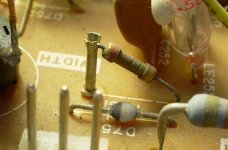
Does anyone know what Ohms these require? The ones on the board seem a little.. I won't say burned but dark...
The coloured rings on them are all "burned" colour.. If that makes any sense :p
The first ring is green.. One half of the resistors are elevated for some reason o0
 
Does anyone know what Ohms these require? The ones on the board seem a little.. I won't say burned but dark...
The coloured rings on them are all "burned" colour.. If that makes any sense :p
The first ring is green.. One half of the resistors are elevated for some reason o0
From the schematic and post #93: 56 ohms.
 
Thanks! I forgot you posted that above; I'm not really any good (yet!) at reading schematics, I see the 56 beside the R753 in the schematic; does the 1/4 mean 1/4 watts? (Just checking to make sure I get the right ones - and for the sake of learning a bit about schematics)
 
Thanks.
RS-Components only have carbon composite in stock... I will check around some local stores tomorrow to see if they stock diodes...
Cheers :)
 
Carbon will do in a pinch, but they are bigger and you might have a little trouble fitting it in the space, but you can kludge it.
No problem with space, but I wonder why R751,752 and 753 are mounted so oddly, diagonally with one end at board level as usual and the other end attached to the top of a 1/2" 'standoff'; anybody have an idea?

R751.JPG
 
No problem with space, but I wonder why R751,752 and 753 are mounted so oddly, diagonally with one end at board level as usual and the other end attached to the top of a 1/2" 'standoff'; anybody have an idea?

If the resistors are running too close to the 1/4 W rating, they probably get pretty hot. Are they a current limiter or providing short circuit protection? If so I wonder if there is another problem lurking in the brightness circuit?
 
If the resistors are running too close to the 1/4 W rating, they probably get pretty hot. Are they a current limiter or providing short circuit protection? If so I wonder if there is another problem lurking in the brightness circuit?
Yeah, that's what I'm inclined to think, that with a low value like that they're at least in part meant to be a fuse. Better get 3 or 4 while you're at it ;-)
 
No problem with space, but I wonder why R751,752 and 753 are mounted so oddly, diagonally with one end at board level as usual and the other end attached to the top of a 1/2" 'standoff'; anybody have an idea?

View attachment 11623

I replaced mine with standard carbon resistors. I believe that one end is raised like that as they are basically designed to be like a fuse and blow if there are power issues. If they blow then it's best that they don't blow or burn a hole in the motherboard, hence being raised...please correct me if I'm wrong.

Phil
That's my guess as well.
 
Thanks guys, it has been fun! :D
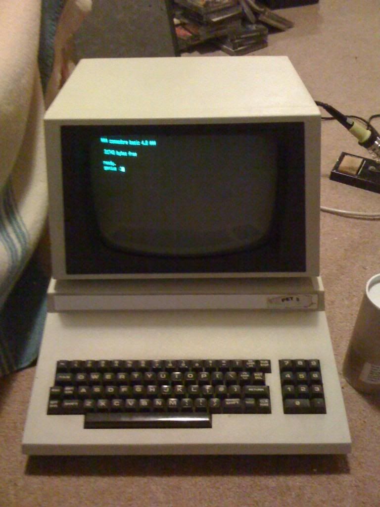
The information supplied by Nama proved to be true.. I guess this could be a common (monitor) problem for those experiencing the same symptoms.. expecially if they're to act as a fuse... good info to have..
IMG_0388_zps32f298df.jpg

IMG_0390_zps0d392658.jpg


Forgive my crappy iPhone gen 1 camera...

Thanks, I really appreciate it!
 
Sorry for jumping in here. I haven't read all the post (there are a lot), but the dead monitor symptoms sound very similar to the problem I was having with my PET 64:

http://www.neoncluster.com/projects-pet/pet-64repair.html

The issue turned out to be a dead resistor on the video board...I believe the resistor was meant to act like fuses and blow if too high voltages were present.
however I can't remember if the monitor in the PET 64 is the same as the 8032 or not.

Phil

This information helped me to fix my CBM 8096 monitor.
That page is gone but it's still available at waybackmachine :)
https://web.archive.org/web/20140414173954/http://www.neoncluster.com/projects-pet/pet-64repair.html
 
The content of thread also fixed the "dead" screen of my PET4016, replacing R752 and R753 with new 56Ohm 1/4W resistors brought it back to life. One of the resistors was OL and the other was fine. Replaced both though ...
 
Back
Top