• Please review our updated Terms and Rules here

Commodore PET Universal 8032086 measurements

johnq

Experienced Member
Joined
Sep 24, 2022
Messages
64
Location
Manchester UK
I'm busy with a project to, as close as possible, recreate the PCB layout from scratch for the Commodore PET Universal 8032086.

About 95% completed and have been using the schematic diagrams and hi-res pics of the motherboards to re-create the PCB layout.

During the reverse engineer I've found what looks like a few design faults.

Is there someone with a 8032086 and a multimeter that can take 2 continuity tests for me.

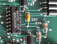
1) Test across C37 - on the PCB looks like this component is shorted with traces. (Not a big deal as it's a decoupling cap)
2) Measure from UB17 (MC3446) to ground. On the schematic this shows it's connected, but I can't see it connected on the PCB. I can't how the PET works without this connection so there must be a connect to ground I'm just not seeing.

Both components are top right, next to each other.
 
Nice going.

I can't see that C37 and/or UB17 are tracked as you say.

There must be a 0V/GND connection to UB17 pins 4, 8 and 12. Pins 4 and 12 are signal inputs that should be connected to 0V (in this application) for correct operation. Pin 8 is the 0V/GND for the MC3446 device, and this MUST be connected to 0V/GND.

I suspect that C37 (as a decoupling capacitor) should be firmly connected between UB17 pin 16 (+5V) at one end and UB17 pin 8 (0V/GND) at the other end. Each of these should be connected to +5V and 0V/GND respectively.

Any chance of posting a high resolution photograph of the PCB traces (top and bottom) around the area concerned?

Dave
 
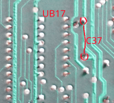
For C37, the trace shows a short on the bottom later (Image is mirror so it matched the top layer)
top.png

bottom.png

On UB17. I forgot to add, it's only pin 12 that I can't see a connection for.

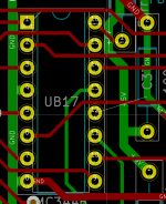
I can't see under the chip, but from the reverse engineering I've done I can't see a way that the trace is routed to GND which has me stumped as this is needed.

Screenshot from 2023-12-04 11-48-17.png
 
You are absolutely correct about C37. I see you have fixed that blooper.

I think your pin 6 appears to be routed between UB17 pins 12 and 13. On the original PCB it looks like pin 6 is routed between pins 11 and 12 (i.e. one too high). If this is the case, I can route a 'red' track between UB17 pins 4 and 12.

Dave
 
hahaha. Long blind already.

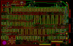
Just about done with this now. Will get a PCB made up and assemble. Once confirmed all working (hopefully) I'll publish the schematic/gerbers etc.

1701697262076.png
 
Wow, your pcb is an amazing effort.

It is interesting the pcb defects that can exist and don't get noticed until somebody reverse engineers it.

When I did the Votrax TNT pcb I found there was a missing section of track work in the power supply section that disconnected an electrolytic cap. But due to the nature of the circuit, it still worked and the manufacturers didn't notice it.

Also, there was a classic track switch around in the original Atari arcade Pong game. Each track carried the least significant bit of the player paddle data. So it turned out, that when the ball interacted with the paddle, the result got affected sometimes from the position of the other player's paddle on the screen. It produced a kind of random spooky effect, and it took 40 years before it was discovered by a fellow who reverse engineered the pcb. I named it "The Ghost in the Machine" after the remark in the iRobot movie.
 
Last edited:
Back
Top