• Please review our updated Terms and Rules here

Compaq Portable + Compaq EGA

That's very nice... I'm hoping I can figure out how to modify the Vide7 EGA card to output EGA on the internal monitor it has a feature connector much like the IBM EGA card so I think I can pull the TTL signals off there.

Also I think if you have an XT-IDE in there you could modify it's BIOS to poke the right registers on the card to put it into the mode you want...
 
That's very nice... I'm hoping I can figure out how to modify the Vide7 EGA card to output EGA on the internal monitor it has a feature connector much like the IBM EGA card so I think I can pull the TTL signals off there.

The internal monitor is using an analog signal, so you'd have to find a way to convert the TTL signalling to analog.

I suspect a good deal of video card manufacturers produced adapters for the feature connector to output to the portable monitor, like the way ATI did for the EGA Wonder. But I've never seen one. Who knows how many are in landfills :(
 
So... basically resistor ladder maybe some pots, and an a good OPAMP that sounds like what a guy did in another thread but he didn't post a schematic of his work.
 
Last edited:
About building a converter.
there is a picture from his work i have been looking at it.
The TTL-CGA to Analog RGB part is easy i have done it in the past to use a scart tv like a monitor it just a few diodes and not much else.
But i am not sure how to combine the RGB lines into a single one this must be done for the mono monitor.
The other issue is the op amp thing it is needed for what for the video signal ? or the sync ?.
 
The OP amp allows you to measure a voltage without affecting it much (as it has a very high input impedance)...

So you'd use diodes and resistors to combine the 3 signals, the diodes prevent backfeeding, and the resistors would be tied to ground on one end and you'd measure the mixed signal with the opamp (wired for unity gain) and take it's output straight to the monitor... just one signal.

Instead of resistors you could use trim pots so you could adjust them to your liking...

In this basic configuration any one color alone would would drive the monitor equaly... if the resistors were equal. Probably the easiest thing to do would be to run a monitor test program... and adjust the pots untill all levels are distinct.... unfortunately since this is mono you only really get like 16 or so levels of intensity not separate colors.

I'd suggest mocking it up on a breadboard first to try it out... you'll need at least 3 diodes, a 3 trimp pots and an opamp preferably a fast one but probably any good opamp will sort of work (start with a fast model of the 555 rated for 5V at least single rail, some opamps can have + and - rail voltages), you can test your op amp with by inputtting a voltage on one side and testing the other... it should input voltage should follow the output voltage if you have it setup correctly. You could do it without the opamp probably... but it can only help to have it there as it acts as an analog buffer effectively isolating your resistors and diodes from the CRT.

Trim pots have 3 legs 1 2 3... 2 is the wiper typically, what you are going to do is tie the wipers together on your pots and then through another resistor to ground (try 10k to start with with grandually smaller values). leg 1 will go to the input signals and leave leg 3 floating... you'll put the diodes pointing toward the inputs of your trim pots... the op amp input is connected to all 3 wipers on your trim pots, is wired for unity gain (look it up) and te output will go to your monitor... hopefully this is helpful I haven't tested it yet but this is what I plan to try. An asorted set of trim pots is like $5 on ebay, and you can get some opamps cheap also, I forget what model was suggested in the other thread but probably grab one of those and an LM555 also those are super useful anyway for all sorts of things. also you can use leg 1 and 3 of a trim pot as just a plain resistor... for whatever value the trim pot is. The assorted sets usually have a few lower values, and 1k 10k 50k and 100k pots search for 3296W its a small pot that should work.

In case you don't know the way a potentiometer works is there is a resistive strip inside, that is the value the pot is rated at from pin 1 to 3, pin 2 is connected to a metal wiper, that runs along the strip and connects you to some resistance between 0 and the rated resistance by turning the pot screw. You can see this easily by setting a multimeter to ohms connected to pin 1 and 3 and you'll see the pot value, connect to 1 and 2 and you'll see the resitance change as you turn the pot... the same goes for 2 and 3 its just the opposite portion of the resistance.
 
Last edited:
The OP amp allows you to measure a voltage without affecting it much (as it has a very high input impedance)...

So you'd use diodes and resistors to combine the 3 signals, the diodes prevent backfeeding, and the resistors would be tied to ground on one end and you'd measure the mixed signal with the opamp (wired for unity gain) and take it's output straight to the monitor... just one signal.

Instead of resistors you could use trim pots so you could adjust them to your liking...

In this basic configuration any one color alone would would drive the monitor equaly... if the resistors were equal. Probably the easiest thing to do would be to run a monitor test program... and adjust the pots untill all levels are distinct.... unfortunately since this is mono you only really get like 16 or so levels of intensity not separate colors.

I'd suggest mocking it up on a breadboard first to try it out... you'll need at least 3 diodes, a 3 trimp pots and an opamp preferably a fast one but probably any good opamp will sort of work (start with a fast model of the 555 rated for 5V at least single rail, some opamps can have + and - rail voltages), you can test your op amp with by inputtting a voltage on one side and testing the other... it should input voltage should follow the output voltage if you have it setup correctly. You could do it without the opamp probably... but it can only help to have it there as it acts as an analog buffer effectively isolating your resistors and diodes from the CRT.

Trim pots have 3 legs 1 2 3... 2 is the wiper typically, what you are going to do is tie the wipers together on your pots and then through another resistor to ground (try 10k to start with with grandually smaller values). leg 1 will go to the input signals and leave leg 3 floating... you'll put the diodes pointing toward the inputs of your trim pots... the op amp input is connected to all 3 wipers on your trim pots, is wired for unity gain (look it up) and te output will go to your monitor... hopefully this is helpful I haven't tested it yet but this is what I plan to try. An asorted set of trim pots is like $5 on ebay, and you can get some opamps cheap also, I forget what model was suggested in the other thread but probably grab one of those and an LM555 also those are super useful anyway for all sorts of things. also you can use leg 1 and 3 of a trim pot as just a plain resistor... for whatever value the trim pot is. The assorted sets usually have a few lower values, and 1k 10k 50k and 100k pots search for 3296W its a small pot that should work.

In case you don't know the way a potentiometer works is there is a resistive strip inside, that is the value the pot is rated at from pin 1 to 3, pin 2 is connected to a metal wiper, that runs along the strip and connects you to some resistance between 0 and the rated resistance by turning the pot screw. You can see this easily by setting a multimeter to ohms connected to pin 1 and 3 and you'll see the pot value, connect to 1 and 2 and you'll see the resitance change as you turn the pot... the same goes for 2 and 3 its just the opposite portion of the resistance.

Very good info i like to build it so but i'm a little lost on this to start from scratch.
According to this thread: http://www.vcfed.org/forum/showthread.php?50640-EGA-on-built-in-CRT-of-Compaq-Portable-1
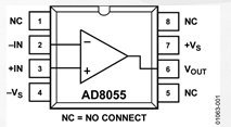
The guy used that do it used an AD8055 op amp, from the picture he showed seems to be like you say resistors the op amp and trimmers:
 
AD8055 should be connected as

1 = no care
2 = 6
3 = input
4 = ground
5 = no care
6 = output
7 = 5V supply
8 = no care
AD8055.PNG

It appears that the RGB signals from the feature connector go to a resistor, which then jumps to pin 1 on each trimmer, then the wipers are all connected together on one row, this is the input to the opamp. Also no diodes appear to be used which is probably why there is an resistor on each input instead of relying only on the trimmer.

Not sure what the extra 3 signals are? Maybe a voltage divider is being made with the trimmers per color channel? note how the wires are G G B B and R R coming from the card i think... its a bit of a mess to see though.

Regardless experimenting with an opamp in unity gain mode should be pretty safe.... for the CRT.

Each alternating pair of trimmer wiper outputs seem to be wire to a single column on each side of the breadboard.

Also can confirm he is running his opamp in unity gain mode there is a red wire between pin 2 and 6.

Note all the wires running to ground on the opamp pin 4.

Yellow wire from pin 6 to the CRT connector is the output.

Also note AD8056 is an alternate part with 2 opamps inside and different pin mapping, you might find it cheaper.
AD8056 pinout:
1 = output
2 = 1
3 = input
4 = ground
5,6,7 = another op amp.
8 = 5v
 
Last edited:
Ressurecting this awesome topic once again :)
I was planning to make a little breakout board for my Portable as well using my ATi vip card but thanks to Resman's photos I managed to find one of the unobtainium (or maybe less easy obtainium ;-) ) CEGC cards (Compaq Enhanced Graphic Cards) sitting inside of a poor Portable II I just bought on Ebay.. Cost me an arm and a leg to ship it to the Netherlands but it's worth it once I swap this card out with my good VDU and sell the II locally (they are very rare and sought after in Europe). I might end up keeping it like all of the other 120 computers that somehow ended up living inside my house *LOL* :)
 
They were harder to find before the Computer Reset liquidation. Quite a few made it back into the wild.
 
Can you please share some decent quality photos or front and back?

If you can, also dump the bios please.

I hope to buy a Compaq EGA card as well some day.
 
Can you please share some decent quality photos or front and back?

If you can, also dump the bios please.

I hope to buy a Compaq EGA card as well some day.

I will once I receive it from across the pond. It'll take I while, especially with Dutch customs..

Check out Ebay ads for (broken) Compaq Portable II machines. Those are the machines that most likely have one of these cards..
 
You'll want to look for a Portable with a video card with (2) RCA jacks and 4 switch module, as follows. This is my Portable with an EGA card:

20230828_110234 (Small).jpg
 
Back
Top