mikerofone
Experienced Member
Hi all,
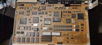
I recently picked up a Compaq SLT 386s/20 at a local flea market. It is missing the power supply, and it has a very nonstandard plug of which I cannot find the pinout.
Q: Does anyone have the pinout, or have its power supply and could measure the voltages?
Long winded post with details
This is said connector:

I'm numbering the pins as follows for reference:
There also is an internal battery, which has four pins:

And I'm numbering these as
Some pictures here: https://photos.app.goo.gl/QVJqG6U6zHF8YZfn8
I'll use P1-P8 for the PSU connector pins, and B1-B4 for the battery pins. Using my multimeter, I was able to determine:
* P1, P2, P5, P7 and P8 are ground pins, as is B4.
* P4 and B3 are directly connected (multimeter beeps).
* P3 isn't directly connected to any battery pin.
* P6 isn't directly connected to any battery pin.
There is an r/vintagecomputing thread that has some pictures of the PSU label, which just reads "18.3V DC, 3A, 33W". The service manual says "Input Voltage
10 - 18.2 VDC" so I guess it's not picky, but there are still too many pins for me to just go randomly poke apply power to them and see what works.
Well, actually, after also seeing in the manual that the battery is rated at 12V, I tried applying 12V+ to B1 and GND to B4. The laptop actually turned on for about 5 seconds and the screen illuminated, but then it shut off and wouldn't boot again. So there is of course a chance that I already caused some damage, though no pops or magic smoke where noticed.
Once I'm done with my current project, I might take it apart and hopefully learn more about the individual pins, but I'm hoping someone might already know the answers.
Cheers
mikerofone
I recently picked up a Compaq SLT 386s/20 at a local flea market. It is missing the power supply, and it has a very nonstandard plug of which I cannot find the pinout.
Q: Does anyone have the pinout, or have its power supply and could measure the voltages?
Long winded post with details
This is said connector:

I'm numbering the pins as follows for reference:
Code:
   3  4
1
   5  6
2
   7  8
There also is an internal battery, which has four pins:

And I'm numbering these as
Code:
1 2 3 4Some pictures here: https://photos.app.goo.gl/QVJqG6U6zHF8YZfn8
I'll use P1-P8 for the PSU connector pins, and B1-B4 for the battery pins. Using my multimeter, I was able to determine:
* P1, P2, P5, P7 and P8 are ground pins, as is B4.
* P4 and B3 are directly connected (multimeter beeps).
* P3 isn't directly connected to any battery pin.
* P6 isn't directly connected to any battery pin.
There is an r/vintagecomputing thread that has some pictures of the PSU label, which just reads "18.3V DC, 3A, 33W". The service manual says "Input Voltage
10 - 18.2 VDC" so I guess it's not picky, but there are still too many pins for me to just go randomly poke apply power to them and see what works.
Well, actually, after also seeing in the manual that the battery is rated at 12V, I tried applying 12V+ to B1 and GND to B4. The laptop actually turned on for about 5 seconds and the screen illuminated, but then it shut off and wouldn't boot again. So there is of course a chance that I already caused some damage, though no pops or magic smoke where noticed.
Once I'm done with my current project, I might take it apart and hopefully learn more about the individual pins, but I'm hoping someone might already know the answers.
Cheers
mikerofone

