• Please review our updated Terms and Rules here

Composite Black and White monitor dead

tezza

Veteran Member
Joined
Oct 1, 2007
Messages
4,731
Location
New Zealand
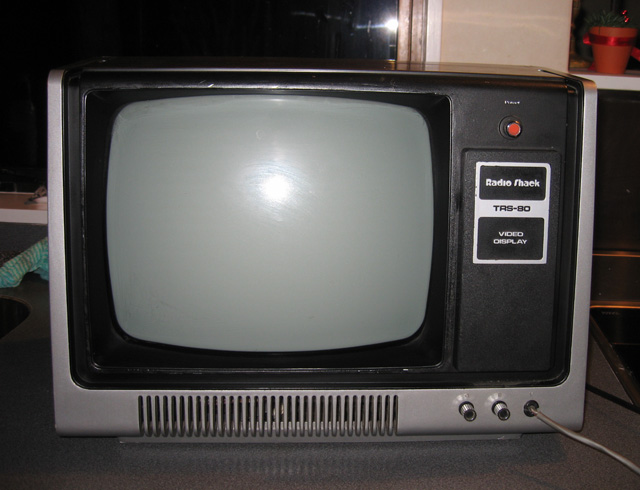
Really it's more than just any old composite monitor...it's actually an acceptable looking TRS-80 Model 1 monitor I snagged for $3 but I figure the principles are the same regardless.

It's dead. No raster and no glow in the tube neck. The board does heat uo though and there is that smell of old electronics being startled awake after many years. I've done no tests yet, but I have Sam's Facts for the model 1, and they provide a troubleshooting guide for the monitor and say what voltages should be on cetain components. I suspect something to do with the AC power supply of maybe horizontal sweep. Some faulty power transistor maybe?

What I would appreciate from anyone who knows, is a link to a page or doc which explains how composite B/W monitors work. The Sam's document is great from the perspective of troubleshooting detail but it does assume you know, conceptually, just what's going on. I don't and I'd like to get some understanding before I start poking around.

Incidently the SAM's fact PDF covers the 110V version while I have a 240V one. There are some differences, one of which is there appears to be no fuses in the AC circuits!

Thanks

Tez
 
It's dead. No raster and no glow in the tube neck. The board does heat uo though and there is that smell of old electronics being startled awake after many years.
Due to the design of the IBM 5151, a good 5151 will present those same symptoms until it is connected to a video card.
Maybe the TRS-80 Model 1 monitor is of the same basic design.
 
Yes, good thought. That is true about the TTL IMB 5151 but I don't think it's the same with these mono composite monitors.

The TRS-80 Model 1 monitor is actually just a modified RCA B/W television (with the tuner bits missing...there are even holes for it on the circuitboard). I've got other monitor like this that I have used as a substitute with my Model 1 keyboard/computer. It certainly shows a raster whether plugged into the computer or not, as do the other composite monitors I have around.

From what I gather these composite monitors basically all work the same way as far as the electronics go. I'd like to know just how these circuits should work, so I can apply some intelligence to the diagnostic process rather than just blindly following steps. Given it's a 240V board and my manual is for 110V there are bound to be some differences in the specifics. If I have a general idea of what should be happening though, I might be able to connect the dots....and not electrocute myself in the process :)

Tez
 
Well, the essentials are a video amplifier and two oscillators, one around 60Hz for vertical deflection and another around 15kHz for horizontal which also generates high voltage for the CRT via the flyback or HOT (Horizontal Output Transformer); they drive the coils in the deflection yoke and magnetically move the beam around. The composite signal is split into a video signal which is amplified and modulates the electron beam, and vertical and horizontal sync signals which lock and synchronize the oscillators to the source. Of course also a power supply, although generally some of the voltages are derived from the HOT which can make it tricky to troubleshoot...

But you probably already know all that.

I'd probably start with finding how the CRT filament is powered and why it's not lit, and following the power supply lines.
 
Last edited:
Have you done a good visual inspection? Spotting a bad solder joint or spotting a bad component can save hours of work.

What test equipment do you have?

You have the circuit diagram. I would first examine the voltage rails produced by the power supply (as different to voltage rails produced by other circuitry).
If those power supply generated voltage rails are good, then it's on to look at other things.
If only one of the power supply generated rails is missing/low, then investigation as to why. Loaded down by a short, or component failure in the power supply?
If all of the power supply generated rails are missing/low, then investigation as to why. Power supply failure, or has the power supply shut itself down due to a short elsewhere?
 
The heater for the CRT is sometimes powered from a winding on the horizontal output transformer; sometimes from the DC supply and sometimes from the winding on a power transformer. The situation with your inexpensive monitor is most likely the first.

Okay, so anything in the horizontal section with a problem will cause the problem you describe. A good place to start troubleshooting is the horizontal output transistor. Does it pass a check with a tester? Is there a signal at the base?
 
The heater for the CRT is sometimes powered from a winding on the horizontal output transformer; sometimes from the DC supply and sometimes from the winding on a power transformer. The situation with your inexpensive monitor is most likely the first.
Yeah, that's what I meant by "tricky"; unlike a "normal" power supply, if the horizontal oscillator's not running there won't be power to various sections (and without power there's no horizontal oscillator ;-) ).

Careful, there can be nasty voltages around the horizontal output section.
 
Thanks guys, I'll take those comments on board. Good high-level overview Mike...it does help. Although I have troubleshot monitors in the past, I didn't have a full understanding of how they work. Getting there though.

I have the usual test stuff, multimeter, scope, logic probe (not need for this probably), a healthy fear of getting zapped etc.

One of the early things SAM's facts says if there is no life is to check that horizontal output transistor so that's what I'll be doing once I start the project. That might not be for a little while but I'll let you know of progress when I do.

One question. With these kind of monitors, what are the likely differences going to be in the circuitry with 110V vrs 240V? Anyone know?

Tez
 
No substantive difference, except for a bit in the power supply. Most of the substantive difference is in the receiver circuitry (the US is NTSC; most of the rest of the world is PAL). By the time it gets to the pure video circuitry, they're pretty much the same--only the frequencies differ.
 
Hmm..interesting. I've got an hour or two spare so I've opened up the back. The 240V feeds straight into a 240v-->110v step-down transformer which then feeds 110V into the board. So that might be the only difference?

One thing I'm not sure about. The SAMS sheet mentions checking for various voltages in the AC power circuit. I'm familiar with DC circuits where you have ground or earth (the ground rail, or where ever the circuit board tells me earth is). When measuring voltages in this AC circuit though, where do you put the black probe of the multimeter if you want to measure the voltage at a particular spot? Is it on the neutral line which comes into the unit? The chassis doesn't seem to be connected to either side of the AC line?

Should I be using an isolating transformer when poking around in this part of the circuitry?

Sorry if these are newbie questions (I am a newbie at this AC-stuff).

Tez
 
Hmm..just looking at this circuit diagram. There are some differences so seems it is more than just the step down transformer and lack of fuses that's different between this and the SAMS diagram.

One weird thing is that there is 520 Ohms connectivity to ground (chassis) on BOTH AC lines coming out of the step down transformer. Is this unusual? The circuit diagram has one line going straight to earth. However, earlier on in the manual it talks about some monitors being "Hot chassis" (Chassis solidly connected to one of the AC lines), some having a secondary ground system which is "Non-isolated" and still others that have an 85V RMS potential to from chassis to earth ground regardless of the AC polarity.

There is no connectivity to ground and the 240V lines going in.

The horizontal output transistor doesn't seem to have any voltage obvious on any of it's pins.

Time to put this away for now. I'll get back to it later.

Tez
 
Do some Internet research on 'hot chassis'. It can affect how measurements are taken. It some cases you can damage test equipment. For example. You may assume that the metal internal chassis of the monitor is connected to the earth wire coming in to the monitor via the 240 Vac plug, but in a 'hot chassis' scenario, it is not. Depending on design, the 'hot chassis' may be sitting at a full 240 Vac with respect to earth. Attach the ground lead of your cro probe to a 'hot chassis'and you'll see the lead melt. This is one of the reasons why why techs use external isolation transformers when working on 'hot chassis' devices.

The main reason for the use of 'hot chassis' design was to get rid the heavy/bulky/expensive isolation transformer in the power supply.

If the 240/110 step down transformer you write of is such that the primary and secondary coils are isolated from each other, then you don't have a 'hot chassis', however if the transformer is of the auto-transformer type, then the possibility of a 'hot chassis' exists.

With power off, measure the resistance between the monitor's metal chassis and the earth pin on the 240V plug. If zero ohms (or about), then you don't have a 'hot chassis'.

Even with no 'hot chassis', you still need to be careful within the power supply as parts of it could be isolated. For example. You may see a switchmode controller IC, look up the specs, and from those specs see that the the IC power source is supplied via pins 5 and 20, with pin 5 the negative pin and pin 20 the positive pin. It would be an assumption to think that pin 5 is sitting at earth potential.
 
One weird thing is that there is 520 Ohms connectivity to ground (chassis) on BOTH AC lines coming out of the step down transformer. Is this unusual?
It comes down to the design.

To measure the 110 Vac out of the transformer, use a multimeter per:
240_110.jpg
 
If both of the AC lines feed a full-wave bridge, you're going to get some resistance to chassis ground, since neither is connected directly to chassis. Try to trace them and see where they go.

When I first used my Altair 8800 with a TV Typewriter, I used a Zenith portable tube (not just the CRT) hot-chassis TV. Back then, the AC plugs weren't polarized--safety depending on there not being any exposed metal parts at chassis potential. I got a couple of nasty shocks out of that setup.
 
If the 240/110 step down transformer you write of is such that the primary and secondary coils are isolated from each other, then you don't have a 'hot chassis', however if the transformer is of the auto-transformer type, then the possibility of a 'hot chassis' exists.

With power off, measure the resistance between the monitor's metal chassis and the earth pin on the 240V plug. If zero ohms (or about), then you don't have a 'hot chassis'.

There is no earth wire...only the neutral and phase come from the plug.

Hmm. I'll digest what I know so far, do some more reading and work on this further in the week. Thanks for the help guys.

Tez
 
There is no earth wire...only the neutral and phase come from the plug.
So potentially (pun intended), you may have a hot chassis. Until you establish exactly the situation you're in, work with only the multimeter, and don't earth yourself.

One reason why you possibly don't have a hot chassis when there is no earth connection is that in many countries, such as Australia and New Zealand, the neutral line is earthed at various points in the distribution chain (Multiple Earth Neutral [MEN] or Protective Multiple Earthing [PME]). If the metal chassis in your monitor is connected to the neutral line (something I've not seen), then the chassis will effectively be earthed (well, somewhat earthed).

Are you able to post a link to the circuit diagram?
 
Tony Duell from the Classic Computer mailing list has some familiarity with this monitor and it seems the step-down transformer is also an isolating transformer so there is no hot chassis. This makes me a little more comfortable working around the unit.

I'm working from SAM's Computerfacts for the model 1 which contains a schematic. However the circuit diagram doesn't quite seem to conform to what I've got after the 110V gets to the board. For example there are no fuses and other differences. Tony Duell mentions that the fact that an isolating transformer exists means (quote) "the video input no longer neeeds an optoisolator. The PCB in palce of the IFs stirp, etc, is just a simple transisotr video ampliifier."

What I'll do is to take some detailed close up photo of the circuitry and some measurements at what seem to be key points. I'll post these up.

Tez
 
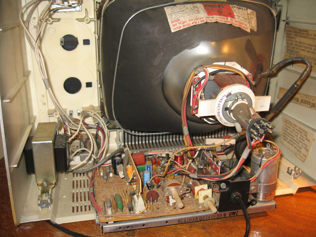
Just some images so you can see what I'm trying to fix. As I said, I'll post some hi-res ones up of the circuitry with some readings when I get a chance.

2012-07-03-model1-monitor.jpg


2012-07-03-inside-model1-monitor.jpg


Note the step-down transformer on the left. I've fixed the bracket on the top left hand corner so the screen is now snugly secured.

Tez
 
Last edited:
Back
Top