Ok, here is an update.
First, the first few components up to C113 seem different than the SAMS schematic (This is in the SAMs document in an earlier link but I have
just the schematic itself linked here).
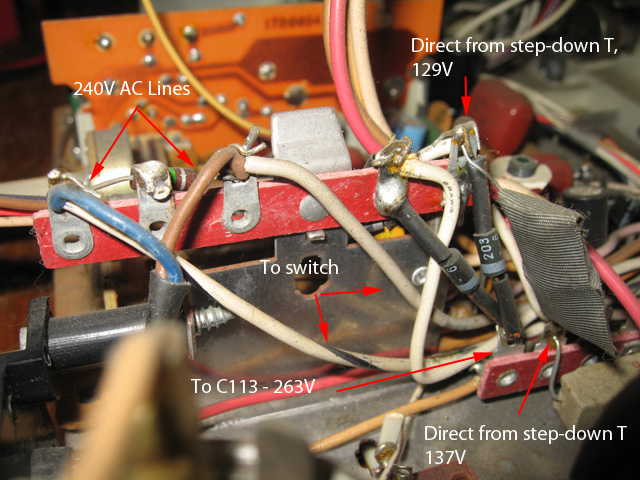
Measuring across the two AC lines after they leave the isolating transformer shows 115V. I traced the two lines through until they connected to other components. Measuring voltage from the two lines when they link up to the first piece of circuitry to ground, gives the voltages shown on the following picture. One line gives 129V, the other 137V. I've shown where they connect.
The yellow wire shown (arrow points to lug it's connected to) goes to C113, - Voltage is 263V? SAMs (and Chuck) says this should be 133V. It seems to be double?? The other lug on C113 measures 172V. I've checked these voltages several times.
Figure 1
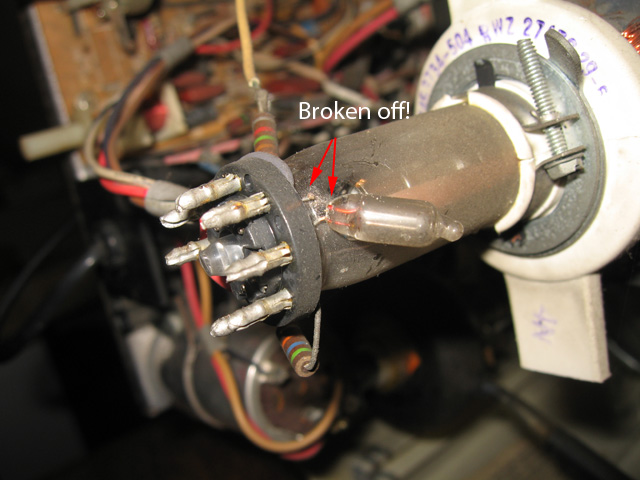
There is another thing I noticed tonight. One of the legs of a small component attached to the bottom of the tube has snapped. I'm not sure how important this component is...or even what it is...it looks like a clear LED. Anyway, here's a pic.
Figure 2
Any advice on what this is and how to replace it most welcome.
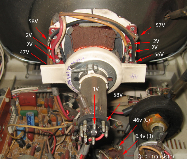
So..it seems like some unusual voltages are floating around this circuit but on the other hand, it's not the same as the schematic either so maybe they are normal? The mutimeter seems to be working ok as it does accurately measure 240V and 115V respectively prior and after the step down transformer across the two lines.
The ground or reference point I'm using to measure the AC voltages (apart from across the two wires prior and after the step-down transformer) is a lug off C113...which is directly wired to the chassis.
Tez