• Please review our updated Terms and Rules here

Cromemco dazzler replica project

Nope,

The 'emulator' is within asm80.com.

Of course, you can't 'see' anything. I am using the memory examination facilities to look at the data bytes that the dazzler would be displaying...

Dave
 
Nope,

The 'emulator' is within asm80.com.

Of course, you can't 'see' anything. I am using the memory examination facilities to look at the data bytes that the dazzler would be displaying...

Dave
Oooh ok I remember having read that z80pack had Dazzler support so just figured you were using that to at least view your output. :) Do you think it would work with z80pack?
 
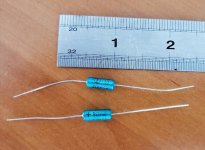
On the topic of those 10uF capacitors, by far the better part is the mil spec stype axial Tantalum. These types don't have a penchant for shorting out like the bead types. You won't have to worn't about them, they have no significant electrical leakage and never require re-forming, they never leak either, the end is a glass seal (not rubber) and they have a low ESR. At a glance they look like an electrolytic. I avoid electros in most things where I can.

Kemet make a lot of them, and they are available with a clear sleeve and sometimes a blue one. Photo attached. These are the ones I used on my Dazzler boards. Also, if you look at the boards, I used the vintage style brown disc ceramic bypass caps, to give it a period correct look, rather than the modern blue small monolithic ceramic types.
 

Attachments

  • 10UF.jpg
    10UF.jpg
    128.2 KB · Views: 2
On the topic of those 10uF capacitors, by far the better part is the mil spec stype axial Tantalum. These types don't have a penchant for shorting out like the bead types. You won't have to worn't about them, they have no significant electrical leakage and never require re-forming, they never leak either, the end is a glass seal (not rubber) and they have a low ESR. At a glance they look like an electrolytic. I avoid electros in most things where I can.

Kemet make a lot of them, and they are available with a clear sleeve and sometimes a blue one. Photo attached. These are the ones I used on my Dazzler boards. Also, if you look at the boards, I used the vintage style brown disc ceramic bypass caps, to give it a period correct look, rather than the modern blue small monolithic ceramic types.
Well, already pulled the trigger on the electro's.. I'll test them when they come in.. Fortunately, caps are easy to replace should I ever need to. Regarding the disc bypass caps, I found these: https://www.ebay.com/itm/285705129002 - not sure I could ever possibly use them all but seems like a good deal. :)
 
looks like a good deal.

I went back through my Mouser order and was able to find some disc alternatives for roughly the same price, not sure why I couldn't find them the first time through. Unfortunately neither Mouser or Digikey have any .1uF bypass disc caps for a reasonable price so I'll just load up on those with that bag on eBay.

Also I have no idea if I chose the right inductor for L1,L2. That seem right? https://www.mouser.com/ProductDetail/815-AIAP01220KT
 
Can anyone who has the GRAPHZ80.REL library link it with a noddy program and upload the resulting executable image for me to disassemble please.

Cheers in advance,

Dave
I was able to track down a copy (on disk 948 Dazzler Graphics in the Cromemco repo) - if you can give me the commands, I can try to get you the resulting file. Attaching the full disk contents here, since I'm assuming some of these .com's were built using the library - includes both .rel's too.
 

Attachments

  • 948 Dazzler Graphics.zip
    107.6 KB · Views: 9
you can use 'Disassemble libraries' utilities for CP/M however you can find the information in the manual i posted as well.

there is new assembler code on the S-100 website, that covers sound.

If you want to start programing for the dazzler today you just need the Cromemco compiler and linker which is freely available and you can make Z80 CP/M 2.2 or 3 binaries.

Just read the manual and it covers how to do everything and the demo disks have the original code used to make the Dazzler demo and shows you how to use the libraries.

when using the Dazzler you will need a Z80 running at 4mhz. yes 2mhz will work as with the released demos from 1977.

there is also broken down code for spacewar but its really not very useful.

the provided RELs (libraries) are a black box but still very functional and you can add to them or use them to make higher level subroutines.

you already have mode, pixel, line, text support at your fingertips. its all in the manuals.

in the 948 Dazzler Graphics.zip above you already have the code demo to use the libraries.

its GDEMO.Z80
and you have the fortran demo code as well to use the other provided libraries.


I forgot Cromemco Also had their own version of basic with the dazzler routines built in, again its all in the manual, so you could write basic programs under C DOS(their version of Cp/M) and create binaries.
however your either trapped in CDOS or it went into the later computers that Cromemco designed and sold with paged ram, ZD1, computers etc. the high nibble offers a simulated version of the cromemco
and everything is coming out of the Z80Pack. that is the graphx.com that loads on top of the Cromemco basic and adds the dazzler extensions so you say things like CALL LINE_DRAW from basic. all that again has to go
through CDOS and not Cp/M.

if i remember there is also a few different version of Cromemco assembler. the big issue is the Cromemco is more limited with Label name sizes, and it makes managing large assembler programs a huge pain.
Microsoft assembler will allow Long name labels but it truncates to 6 characters during compile. it takes a little effort to convert most assembler code to work with Cromemco but its not bad.
you just have to be willing to not use your favorite assembler in favor Cromemco.

SASM was close to working with the Cromemco RELs but you get a half working demo if you try.
 
Last edited:
Well, already pulled the trigger on the electro's.. I'll test them when they come in.. Fortunately, caps are easy to replace should I ever need to. Regarding the disc bypass caps, I found these: https://www.ebay.com/itm/285705129002 - not sure I could ever possibly use them all but seems like a good deal. :)
The "correct" Centralab 0.1uF Y5F seems quite hard to find. This one https://www.ebay.com/itm/175418525140 is close, but far too expensive. Guess you found a good value, also usable for other projects.

The proper TO-220 heat sink might be an ASSMANN WSW V5234B-T (see https://www.ebay.com/itm/264470891693 or https://www.conrad.de/de/p/assmann-...x-b-x-h-18-x-25-4-x-7-9-mm-to-220-183882.html). Could not locate it at Mouser or DigiKey yet. But this is really just a detail.
 
Last edited:
I went back through my Mouser order and was able to find some disc alternatives for roughly the same price, not sure why I couldn't find them the first time through. Unfortunately neither Mouser or Digikey have any .1uF bypass disc caps for a reasonable price so I'll just load up on those with that bag on eBay.

Also I have no idea if I chose the right inductor for L1,L2. That seem right? https://www.mouser.com/ProductDetail/815-AIAP01220KT
For the particular application, the inductors are under very low stress , just a signal application, any small axial inductor of the correct length to fit and value will be ok. The ones you selected look fine. The self resonant frequency of them should be much higher than the operating frequency.
 
>>> Do you think it would work with z80pack?

It should do!

Actually, if you could just post the REL file for me I can do the rest while waiting fir BT OpenReach to install our fibre internet connection at Church...

Dave
 
Seen it.

Been somewhat busy with BT OpenReach who decided to cancel the fibre install at our Church without telling anyone!

I will have a look later.

Cheers.

Dave
 
On the hardware side of things, when I was drawing up the board foils and checking everything against the schematic, I found that oddball scenario I had never seen before, where a flip flop was forced to change state by driving a signal onto one of its outputs. It works because the particular FF, the output pin can act as an input, it is connected to the input of a gate inside the IC package.
 
@Gary C did a fabulous job with the PCB design in KiCAD based on Hugo's work, extremely accurate, really impressive!!!

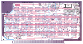
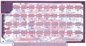
After performing a first visual check, I had the following few findings:

Pin 10 of IC 23 should be connected to Vcc. Same applies to pin 14 of IC 39 and pins 13 + 14 of IC 43. Otherwise, these chips probably won't work or at least not necessarily as they should. All of those are easy to fix if you have already used Gary's design for producing your own boards.

Everything else is of cosmetical nature, and only matters if you want to be closest to the original:

There are some details which have no effect on the function, e.g. the tracks between two adjacent pads are in some cases not exactly at the positions as they are n the orginal PCBs, such as pins 1 + 2 of IC 17, pins 2 + 3 as well as pins 10 + 11 of IC 25, or pins 1 + 2 of IC 74. Or the track from pin 9 of IC 73 has one more corner. For the original boards, the width of the edge connector fingers seem to be equal for all fingers.

Also only of relevance for a good visual match with the original boards are the silkscreen component outlines/symbols which are missing in the design (for capacitors, resistors, XTAL and some more). Same for the IC reference numbers (IC1 to IC73). We probably might better use the IC number as reference designator in KiCAD, and the IC type (7401 etc.) as value property, and position them both in the silkscreen layer centered below the sockets. Another optimization of the silkscreen would be to use the original fonts (guess the Leroy font family had been popular at the time) and improve the reproduction of the corporate parts (copyright & patent statement etc.).

I used the foils of Rev C for the check, I guess Hugo wrote about the latest revision he was using, I am not sure which revision this was, but Rev C is copyrighted 1975, and there also seems to be a newer revision copyrighted 1977. Also Appendix A in the Dazzler Games manual suggests there might be a version newer than Rev C. It probably would be a good idea to also include the changes which are mentioned in this Apppendix in the KiCAD design or at least apply them as a patch.

I did not do any serious checks against the schematics.

Attached are the Rev C foils that I used

Board 1 Rev C.png

Board 2 Rev C.png
 
After performing a first visual check, I had the following few findings:
Pin 10 of IC 23 should be connected to Vcc. Same applies to pin 14 of IC 39 and pins 13 + 14 of IC 43. Otherwise, these chips probably won't work or at least not necessarily as they should. All of those are easy to fix if you have already used Gary's design for producing your own boards.

Hey that's some great sleuthing! At least it sounds like just a few easy bodge wire fixes.
 
So

IC 43 pins 10, 13 & 14 all need connecting to the adjacent rail
IC 39 pin 14 needs connecting to the adjacent rail
IC 23 pin 10 needs connecting to the adjacent rail

Hugo, I notice in the image you sent me, that IC23 pin 10 is not connected ?

I have updated the Kicad PCB files but not yet produced Gerbers as its some time since I did it and can't remember the steps.
 

Attachments

  • Dazzler2.zip
    929.7 KB · Views: 3
  • Dazzler.zip
    951.3 KB · Views: 3
So

IC 43 pins 10, 13 & 14 all need connecting to the adjacent rail
IC 39 pin 14 needs connecting to the adjacent rail
IC 23 pin 10 needs connecting to the adjacent rail

Hugo, I notice in the image you sent me, that IC23 pin 10 is not connected ?

I have updated the Kicad PCB files but not yet produced Gerbers as its some time since I did it and can't remember the steps.
Good catch! I have one of Hugo's boards - and indeed, IC23 pin 10 is not tied to Vcc as it should. Fortunately the board still works since this connection (one of the flip-flop "preset" inputs) will float high if disconnected - however I should put a little jumper there to fix this issue "just in case".
 
Good catch! I have one of Hugo's boards - and indeed, IC23 pin 10 is not tied to Vcc as it should. Fortunately the board still works since this connection (one of the flip-flop "preset" inputs) will float high if disconnected - however I should put a little jumper there to fix this issue "just in case".
Yes, the TTL inputs in general show up high if not connected. So in most cases the design will work anyway. Connecting to Vcc, however, will be more stable under certain conditions. But the Dazzler is no elevator controller, and nobody will be harmed in case of a crash :)

In the Cromemco design some chips like IC21 have unused gates with unconnected inputs, which is not a big thing for TTL, but actually the inputs of unused gates should be connected to Vcc, too. At the time, it was usual to leave unused gates disconnected in order to make it easy to re-use them on demand (e.g. for user extensions).
 
Back
Top