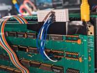
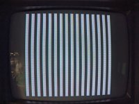
So leave 47 removed, and just insert the temp wiring on 55, correct?2. Remove ICs 47 and 55 from the Dazzler. Insert some temporary wires into the following pins of IC socket IC55 and connect them to 0V: pins 11, 6, 3 and 14.
Upcoming Events:
- VCF South West - June 14 - 16, Davidson-Gundy Alumni Center at University of Texas at Dallas
- VCF West - Aug 2 - 3, Computer History Museum, Mountain View, CA
- VCF Midwest - Sept 7 - 8 2024, Schaumburg, IL
- VCF SoCal - Mid February 2025, Location TBD, Southern CA
- VCF East - April 2025, Infoage Museum, Wall NJ
-
Please review our updated Terms and Rules here
You are using an out of date browser. It may not display this or other websites correctly.
You should upgrade or use an alternative browser.
You should upgrade or use an alternative browser.
Cromemco dazzler replica project
- Thread starter Hugo Holden
- Start date
daver2
10k Member
Correct.
Leaving 47 out will cause the associated outputs to float high (as a result of the IC inputs they are connected to).
Wiring the outputs of 55 to 0V causes them to be low.
All high pins = white. All low pins = black. I hope...
Dave
Leaving 47 out will cause the associated outputs to float high (as a result of the IC inputs they are connected to).
Wiring the outputs of 55 to 0V causes them to be low.
All high pins = white. All low pins = black. I hope...
Dave
daver2
10k Member
That is inspired...
If this works, we can make good use of that!
Dave
If this works, we can make good use of that!
Dave
daver2
10k Member
Yes!
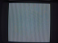
Now can you change D5=1.
This should double the resolution.
Dave
Now can you change D5=1.
This should double the resolution.
Dave
daver2
10k Member
I have to do the washing up now...
Dave
Dave
Yep it does, it doubles the number of vertical lines.Now can you change D5=1.
This should double the resolution.
daver2
10k Member
It should also double the number of horizontal lines - but you won't be able to see that.
Give me a few minutes to finish up in the kitchen and we will try a few other things...
We can have some fun now!
Dave
Give me a few minutes to finish up in the kitchen and we will try a few other things...
We can have some fun now!
Dave
daver2
10k Member
Can you set D7 to D0 as follows (using my test program):
0011 1001
In theory, the display should not change from what it is now.
Dave
0011 1001
In theory, the display should not change from what it is now.
Dave
Can you set D7 to D0 as follows (using my test program):
0011 1001
In theory, the display should not change from what it is now.
Dave
It does not change, still double resolution. The only thing I noticed is setting D4=1 is the lines get very slightly brighter, or potentially like 1 pixel wider.
daver2
10k Member
I can't get too excited about that...
Now set D6=1 and let's see what happens next (or not)...
Dave
Now set D6=1 and let's see what happens next (or not)...
Dave
daver2
10k Member
Well, that should be red - but it looks sort of like cyan/blue to me - but I am green/blue colour blind!
Try various combinations of D2, D1 and D0 from 000 (should be black) to 111 (should be white). The bits 'should' be in the order D2=blue, D1=green and D0=red.
See if you see any difference. We may still need to tweak the colour potentiometers, but don't do that now!
Dave
Try various combinations of D2, D1 and D0 from 000 (should be black) to 111 (should be white). The bits 'should' be in the order D2=blue, D1=green and D0=red.
See if you see any difference. We may still need to tweak the colour potentiometers, but don't do that now!
Dave
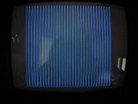
I get no color at all, just varying levels of white. The thin lines may be slightly blue, but could just be an artifact of my monitor.
Some combinations appear to break the lines up..
like this 0111 1101:
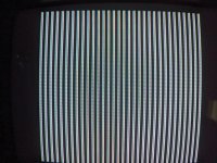
or with D5=0 (0101 1101)
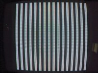
Tried this with 2 known good/working color composite monitors & cables.
Some combinations appear to break the lines up..
like this 0111 1101:

or with D5=0 (0101 1101)

Tried this with 2 known good/working color composite monitors & cables.
daver2
10k Member
Hang on a minute, you are adjusting D7 to D0 in my test program and not the wires connected to IC47 and IC55 aren't you?
Dave
Dave
Yes adjusting the outputs through the test program, not modifying the wires.Hang on a minute, you are adjusting D7 to D0 in my test program and not the wires connected to IC47 and IC55 aren't you?
daver2
10k Member
OK,
Can we do one more test then for tonight.
Set D7 to D0 in my program back to:
0010 0000
Post a photograph.
Then we will tweak some wires next.
Dave
Can we do one more test then for tonight.
Set D7 to D0 in my program back to:
0010 0000
Post a photograph.
Then we will tweak some wires next.
Dave
daver2
10k Member
Next...
Leave IC47 with no wires on it and remove the wires from IC55 pins 11 and 14.
Post another photograph.
Then set D4=1 using my test program.
Post another photograph.
Dave
Leave IC47 with no wires on it and remove the wires from IC55 pins 11 and 14.
Post another photograph.
Then set D4=1 using my test program.
Post another photograph.
Dave

