• Please review our updated Terms and Rules here

Cromemco dazzler replica project

Hugo,

1712217679786.png
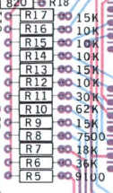
Checking the resistor chain, I notice that the resistors at the 'top' (closest to the video mixer) are connected (in order of the PCB track running downwards):

Lo brightness Colour DAC (R17, R16 and R15).
Hi Brightness Colour DAC (R14, R13 and R12).
Monochrome DAC (R11 to R8).
Colour burst (R7 and R6).
Sync (R5).

Unfortunately, therefore (since we have sync and the colour burst) the entire PCB track chain must be intact.

Dave
 
Hugo,

View attachment 1277256
Checking the resistor chain, I notice that the resistors at the 'top' (closest to the video mixer) are connected (in order of the PCB track running downwards):

Lo brightness Colour DAC (R17, R16 and R15).
Hi Brightness Colour DAC (R14, R13 and R12).
Monochrome DAC (R11 to R8).
Colour burst (R7 and R6).
Sync (R5).

Unfortunately, therefore (since we have sync and the colour burst) the entire PCB track chain must be intact.

Dave
Yes I agree, unless for some reason the other side of the resistors do not connect to the gate outputs of the R,G & B signals, though that is unlikely since I think @nullvalue has checked this and it would take six connections to be open (unlikely)

So a re-check of the video output signal with the scope is in order.
 
So, here is my first draft of a test procedure.

Using RDOS commands...

; Turn the Dazzler ON and set the base address of the display memory to 2000h
O 0E 90

; Normal resolution, 512B display memory (2000 to 21FF), colour mode.
O 0F 10

You should have a random display. It 'should' be in colour but (as we already know) it probably will not be...

; Fill the memory with 'white' - Note, I am filling the entire 2K of memory (2000 to 27FF) for later. Either high brightness white or all pixels ON (depending upon the selected Dazzler mode)
SM 2000 and set the byte value to FF
M 2000 27FE 2001

You should have a completely white screen.

Adjust potentiometer R29 for a stable picture. I assume you have already done this previously?

; Set the Dazzler mode to X4 resolution (D6=1), Picture in 2K memory (D5=1), Colour mode (D4=1), High brightness (D3=1), Blue (D2=1).
O 0F 7C

You now should have a completely BLUE screen (in theory at least).

Check the following IC pins:

IC17 pin 11 - Should be pulsing HIGH.
IC17 pin 9 - Should be HIGH or pulsing HIGH.
IC17 pin 10 - Should be oscillating at 3.58 MHz.

IC16 pin 11 - Should be pulsing HIGH.
IC16 pin 10 - Should be HIGH or pulsing HIGH.
IC16 pin 9 - Should be oscillating at 3.58 MHz.

Check the following pins for pulse trains of 3.58 MHz:

IC17 pin 8.
IC16 pin 8.

Check the video output signal with your oscilloscope. Try and get a stable picture with three (3) synchronising pulses containing two (2) colour bursts and two (2) video lines.

Let's see what we have, both on the screen and the oscilloscope.

Whilst this screen is displayed, move your oscilloscope probe onto IC14 pin 3. This should indicate approximately 3.58 MHz.

Carefully, and slowly, adjust C17 (the variable capacitor) in both directions to see if a BLUE screen magically appears or not. What you are adjusting here is the frequency of the 3.58 MHz oscillator.

If you do NOT get a colour screen at this point - STOP.

If you DO get a colour screen proceed as follows:

; Set the display to a GREEN screen.
O 0F 7A

Adjust variable resistor R28 for the brightest green.

; Set the display to a RED screen.
O 0F 79

Adjust variable resistor R27 for the brightest red.

Now, I think the above (red and green) may be in the wrong order...

After adjusting for RED, go back to the green screen again (O 0F 7A) and see if this has changed. If it has, readjust R28 again.

Test all of the primary and secondary colours as follows:

O 0F 70 - Black.
O 0F 79 - Red.
O 0F 7A - Green.
O 0F 7C - Blue.
O 0F 7B - Yellow.
O 0F 7D - Magenta.
O 0F 7E - Cyan.
O 0F 7F - White.

There are lower brightness version of the above. For example, grey (low brightness white) should be (O 0F 77). By setting data bit 3 to a 0 will give you the low brightness version of the identified colour.

Dave
 
Last edited:
So, here is my first draft of a test procedure.

Using RDOS commands...

; Turn the Dazzler ON and set the base address of the display memory to 2000h
O 0E 90

; Normal resolution, 512B display memory (2000 to 21FF), colour mode.
O 0F 10

Display is black

You should have a random display. It 'should' be in colour but (as we already know) it probably will not be...

; Fill the memory with 'white' - Note, I am filling the entire 2K of memory (2000 to 27FF) for later. Either high brightness white or all pixels ON (depending upon the selected Dazzler mode)
SM 2000 and set the byte value to FF
M 2000 27FE 2001
Ran these commands too, nothing on screen..

I ran your actual test app though and everything is still working as before (get the striped random screen)

But these 3 or 4 commands aren't putting anything on the display
 
Because some idiot (!) got the RDOS output command parameters the wrong way around!

It should be:

O 90 0E

etc.

The port address is always at the end...

Swap the port and data byte value around the other way in my post 😀!

Dave
 
...
; Fill the memory with 'white' - Note, I am filling the entire 2K of memory (2000 to 27FF) for later. Either high brightness white or all pixels ON (depending upon the selected Dazzler mode)
SM 2000 and set the byte value to FF
M 2000 27FE 2001

You should have a completely white screen.
Ok yep I have a completely white screen now :)
 
Adjust potentiometer R29 for a stable picture. I assume you have already done this previously?
Yep this was already adjusted

; Set the Dazzler mode to X4 resolution (D6=1), Picture in 2K memory (D5=1), Colour mode (D4=1), High brightness (D3=1), Blue (D2=1).
O 0F 7C

You now should have a completely BLUE screen (in theory at least).
Done (but not blue, see below)

Check the following IC pins:

IC17 pin 11 - Should be pulsing HIGH.
IC17 pin 9 - Should be HIGH or pulsing HIGH.
IC17 pin 10 - Should be oscillating at 3.58 MHz.
Correct

IC16 pin 11 - Should be pulsing HIGH.
IC16 pin 10 - Should be HIGH or pulsing HIGH.
IC16 pin 9 - Should be oscillating at 3.58 MHz.
Correct

Check the following pins for pulse trains of 3.58 MHz:

IC17 pin 8.
IC16 pin 8.
Correct

Check the video output signal with your oscilloscope. Try and get a stable picture with three (3) synchronising pulses containing two (2) colour bursts and two (2) video lines.

Let's see what we have, both on the screen and the oscilloscope.
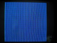
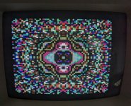
This picture actually does it more justice than it deserves... in person it's like a very dim navy blue..
PXL_20240404_195336129.MP.jpg
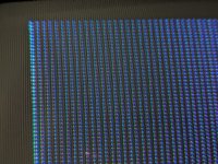
I don't know if it even comes through well in the photo but what's on my screen isn't even a solid color but its made up of a lot of thin vertical lines. Here's a better close-up:
PXL_20240404_201819194.MP.jpg

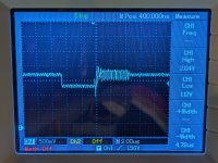
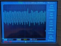
timebase: 2.0us
PXL_20240404_200907699.MP.jpg

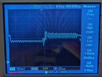
timebase: 1.0us

PXL_20240404_200848031.MP.jpg

Whilst this screen is displayed, move your oscilloscope probe onto IC14 pin 3. This should indicate approximately 3.58 MHz.

Carefully, and slowly, adjust C17 (the variable capacitor) in both directions to see if a BLUE screen magically appears or not. What you are adjusting here is the frequency of the 3.58 MHz oscillator.

If you do NOT get a colour screen at this point - STOP.

I have tried adjusting the capacitor and have not got a nice solid blue. It just stays the same as what I've posted..
 
What type of monitor are you using? Is it a trinitron by any chance?

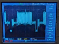
On the oscilloscope trace you have got one sync. pulse and one colour burst. You need to slow down the timebase to get two (2) of these on the oscilloscope screen please.

Dave
 
On the oscilloscope trace you have got one sync. pulse and one colour burst. You need to slow down the timebase to get two (2) of these on the oscilloscope screen please.
This what you need? I adjusted the voltage to 200mV
PXL_20240404_204633332.MP.jpg
 
Yes, the video signal should be 1V peak to peak - so 200 mV/div is about right.

The lowest blip is the synchronising pulse.

The short burst is the colour burst which is what the monitor locks onto for the colour information.

The large burst should be the video signal of one line of blue.

Can you zoom in to see what the 'blue line' signal actually consists of. It should be a 3.58 MHz signal. But we need to see it.

Dave
 
>>> Nope right now just using a Commodore 1701.

Sorry, I need to explain a bit more. A trinitron is a type of CRT that is used in a monitor. It consists of vertical 'stripes' of alternating red, green and blue phosphorus.

Another type of CRT uses a triad of red, green and blue phosphor dots.

Dave
 
>>> Nope right now just using a Commodore 1701.

Sorry, I need to explain a bit more. A trinitron is a type of CRT that is used in a monitor. It consists of vertical 'stripes' of alternating red, green and blue phosphorus.
I'm familiar with Trinitron - I had one for many years.. I'm almost positive the CRT type in a Commodore 1701 is not a Trinitron.. Unless I'm somehow mistaken?
 
I think we need a steer here from Hugo.

It might be worth seeing what is on the other gate outputs from IC16 and IC17 with a (supposedly) blue screen displayed. Using your oscilloscope of course.

If you are seeing red and green, then is this coming from the circuitry or from the monitor?

Dave
 
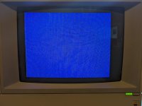
Well hold on now I just plugged it into my AppleColor monitor and the picture is actually blue!

PXL_20240404_211642579.MP.jpg
 
Ah, the monitor lies...

However, it looked black to me - but then I realised my phone was in 'sleep' mode!

Just turned sleep mode OFF, and I see blue!

Dave
 
Back
Top