daver2
10k Member
") ...
...Dave
| VCF West | Aug 01 - 02 2025, | CHM, Mountain View, CA |
| VCF Midwest | Sep 13 - 14 2025, | Schaumburg, IL |
| VCF Montreal | Jan 24 - 25, 2026, | RMC Saint Jean, Montreal, Canada |
| VCF SoCal | Feb 14 - 15, 2026, | Hotel Fera, Orange CA |
| VCF Southwest | May 29 - 31, 2026, | Westin Dallas Fort Worth Airport |
| VCF Southeast | June, 2026 | Atlanta, GA |
... !
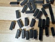
!These LSTTL parts with what looks like a "mermaid" logo have been the topic of several discussions in the S100Computers Google Groups forum. They look like this (photo courtesy of a poster to the S100Computers Google Group):Hey all.
It turns out most of the vertical jumping/jittering was related to U72 (74LS04) on all three boards. Apparently the Dazzler doesn't like the 74LS04 ICs that I used, even though they work on other parts of the board and test fine with a Retro Chip Tester. They are labeled:
24ARSS8E
SN74LS04N
There is a stylized V or something like that to the left of the 24...

Yes but he got caught out for another reason.U72 is listed as an LS part in the Dazzler manual
But those parts look really dodgy.
Yes. Dave asked what the spec was.Yes but he got caught out for another reason.
You could work it out with some tests that an IC tester does not do, but I would not waste my time. Because they are pretending to be something they are not and have been the subject of the refurbishing industry, and even if you could prove what logic family they belonged to, they are totally untrustworthy and belong in the bin because their unknown history likely includes the chance of a lot of electrostatic damage. You would be 100% better off to buy a vintage part in a Radio Shack package from 1985. If you put your mind to it, you can spot fake non vintage IC's from a mile away. There are many features that give the game away.Yes. Dave asked what the spec was.
I wonder what they really are. HCT versions relabled ?

So after VCFMW last year I told myself that I wanted to do a Cyclops exhibit next (this) year - but alas, I'm no closer now than I was then to acquiring a Cyclops or building a reproduction. So I figured in the meantime I could make a simulated version. Here's my first attempt to get something working. It's using a modern computer with a webcam. I wrote a C# program which is converting each frame to a 64x64 image within the Dazzler color palette, and sending the data encoded over serial to a Z80 ASM program I have running which basically just feeds the data into the display. I think it's working well enough that I will continue down this road so I at least have something new/fun for visitors to check out - at least I think they'll have fun waving at themselves. I also have tried the 128x128 mono mode with a few different dithering patterns. Each have tradeoffs but its fun to play around. At 9600 baud over serial I'm getting like maybe 1 frame every 4 seconds (0.25 FPS?). I am going to be switching over to a parallel connection and using the TU-ART, I think I should be able to get up to a full 30FPS then but we'll see. If this all works well, then I'll switch to some kind of full hardware version maybe with an ESP chip.
View attachment 1302982
The are already existing videos available on YouTube for the same demo, but there was no step-by-step tutorial yet.