• Please review our updated Terms and Rules here

Cromemco dazzler replica project

Hugo. OK.

I have compared the circuit in the Patent with the schematic in the manual and there are a small number of differences. I have managed to "hand scribe" a schematic with the symbolic references on it derived from the patent.

I just have to understand it now...

I might enter it into a circuit simulator and see what I get...

Interestingly, there is only one input signal (from D5) into the circuit to vary the pulse output.

Barring an IC fault, a soldering fault or a PCB track fault - I can't see how the pulse train can be out by a factor of 2?

Dave
 
So I have simulated the schematic and found something interesting...

With D5=0 I get 17 pulses and with D5=1 I get 33 pulses (but the first intermediate pulse is missing).

For some reason my IC8/6 pulses are inverted when compared with your oscilloscope traces... Ah I have coded a NAND gate instead of an AND gate - so I can't get too excited about that!

I am beginning to suspect that the test procedure is incorrect...

If the image is in 512B of memory (D5=0) then there are 16 bytes per line.

If the image is in 2KB of memory (D5=1) then there are 32 bytes per line.

Not sure why there is an extra pulse (16 vs 17 and 32 vs 33) but I suspect either the first (or last) pulse perform a unique function other than (or as well as) performing a DMA.

I am now really convinced that the Cromemco manual is wrong.

Dave
 
Last edited:
So I have simulated the schematic and found something interesting...

With D5=0 I get 17 pulses and with D5=1 I get 33 pulses (but the first intermediate pulse is missing).

For some reason my IC8/6 pulses are inverted when compared with your oscilloscope traces... Ah I have coded a NAND gate instead of an AND gate - so I can't get too excited about that!

I am beginning to suspect that the test procedure is incorrect...

If the image is in 512B of memory (D5=0) then there are 16 bytes per line.

If the image is in 2KB of memory (D5=1) then there are 32 bytes per line.

Not sure why there is an extra pulse (16 vs 17 and 32 vs 33) but I suspect either the first (or last) pulse perform a unique function other than (or as well as) performing a DMA.

I am now really convinced that the Cromemco manual is wrong.

Dave

In other TTL logic systems I have analysed, ones which ultimately generate video, timing is everything. When pulses are divided down from a master clock, it helps to use synchronous counters, still later, with whatever pulses are derived they can have an awkward relationship to the rising or falling edge of the clock, elsewhere after the delays of other gates are accounted for, making them dependent on the particular device properties. It is interesting though that they delayed the inputs to IC8 on pins 5 & 4. It might be that there is supposed to be an extra pulse in the train, and it simply gets ignored later due to timing considerations. Or maybe the simulated circuit simply behaves differently. I would have to get my Dazzler running and check with the scope.

I guess the manual could be wrong...... If it was it would have meant, at the time, not many people would have been able to get their Dazzlers working and they would have ended up at Cromemco's repair Dept. You would think they would have picked up on the reason why and sent out an errata sheet.

Looking at the scope recording on post #547 there are 17 pulses there. I agree, one pulse presumably the leading wider one they talk of has another application, so it is out by a factor of 2 with respect to the 16 pulses, that should be 32, something must have gone awry with the gating of the signals from the 74161 counters or possibly the pre-load values of the counters from pin 6 of IC21. That is if we believe the manual. But your simulation agrees with what @nullvalue is seeing, making the manual look very suspicious. But, they seem very definite about what pulses should be there.

When I can clear the bench I'll fire up my Dazzler and check.
 
Last edited:
So I have simulated the schematic and found something interesting...

With D5=0 I get 17 pulses and with D5=1 I get 33 pulses (but the first intermediate pulse is missing).

For some reason my IC8/6 pulses are inverted when compared with your oscilloscope traces... Ah I have coded a NAND gate instead of an AND gate - so I can't get too excited about that!

I am beginning to suspect that the test procedure is incorrect...

If the image is in 512B of memory (D5=0) then there are 16 bytes per line.

If the image is in 2KB of memory (D5=1) then there are 32 bytes per line.

Not sure why there is an extra pulse (16 vs 17 and 32 vs 33) but I suspect either the first (or last) pulse perform a unique function other than (or as well as) performing a DMA.

I am now really convinced that the Cromemco manual is wrong.

Dave
This is good news , and wow, some amazing detective work on your part. What are you using for a circuit simulator? BTW that is also what I was seeing with the 33 pulses (1st intermediate pulse missing) and I think the manual describes that as expect. I thought the manual seemed weird, I did my rudimentary version of math, and with the pulse width they were expecting, the number of pulses they name in manual wouldn't fit in the expected space. Crazy stuff! 2 dogs down, 4 more to go! 😁
 
Last edited:
nullvalue, your requested IC's are being picked up today by the USPO and should take 4-5 days for delivery (plus any delayed caused by the holiday) All are 1980's or earlier date codes and picked for that reason. I included a couple of extra 7404's because I had a bunch of them. Between the guys with knowledge and perhaps some old dated parts I'm sure you'll have the board running soon.
Thanks again Don! With that and the remaining parts I ordered from eBay (literally an hour or two before your generous offer :) ) they should all arrive at about the same time (end of week). Before doing too many more tests I think I may just do the chip swap and go back through all my previous tests and see how it's doing.
 
Last edited:
>>> What are you using for a circuit simulator?

Microsoft Excel spreadsheet!

>>> I did my rudimentary version of math, and with the pulse width they were expecting, the number of pulses they name in manual wouldn't fit in the expected space.

I did the same thing myself, and that is what alerted me to the fact that something looked awry!

Dave
 
There is also a very good, online circuit simulator at: https://www.falstad.com/circuit/.

I use that quite a lot.

Stick an LED and a voltmeter on the output of things to be measured, right click on the voltmeter and add it to an oscilloscope.

Put a switch on the D5 signal and you are good to go.

There is a synchronous, loadable 4-bit counter and basic gates. I would be tempted to use named nodes to create the schematic rather than mess about too much with wiring.

You can save the resulting simulation as a text file, and reloaded it from the text file later.

Dave
 
The two test steps are testing different aspects of the logic.

Test 18 is for the vertical logic.

Test 23 is for the horizontal logic.

In the vertical sense there is a 1:1 correspondence between a line of pixels and the memory. As such, for a 32x32 picture there will be 32 lines and therefore 32 pulses.

On the other hand, for the horizontal line of pixels, 1 byte encodes for two pixels (assuming not in x4 mode of course) hence (for a 32x32 image) there will be 16 memory byte accesses.

I suspect someone just copied the text from test 18 to test 23 and didn't quite change it correctly...

Dave
 
Last edited:
Sounds plausible.

and more interesting than a 332 FPGA based online monitoring system I am trying to help install....
 
Had some time this afternoon :)

1711554903811.png

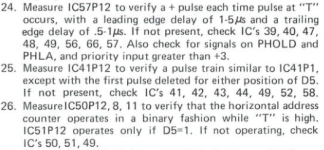
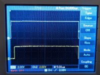
24. This looks good, slight delay on leading and trailing edges. On the pHOLD (bus pin 74) I am seeing the same signal from IC57P12, but inverted. On pHLA (bus pin 26) I see the same signal as IC57P12 (not inverted).
PXL_20240327_155331247.MP.jpg

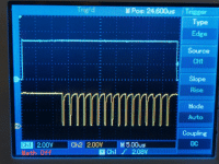
25. On IC41P12 I see a the same signal as IC41P1, with the first pulse sometimes missing. Not sure if this is expected or not. D5=1 does double the pulses, same thing happens with the intermittent first pulse. Here's what it looks like on the scope (D5=0):
ezgif-5-eda03e701e.gif

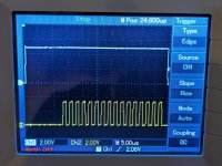
26. This says IC51P12 only operates with D5=1, but with D5=0 I do see 8 pulses. D5=1 I see 16 pulses.

On P8, I see D5=0: 2 pulses, D5=1: 4 pulses

On P11, I see D5=0: 1 pulse, D5=1: 2 pulses

P12 D5=1:
PXL_20240327_161133549.MP.jpg
 
I'll have a look presently.

Got side-tracked with real work. TTL signal pins do NOT like +/- 24V sticking up them... The chip(s) tend to object...

Frying tonight...

I think I have got to the bottom of what someone did...

Dave
 
Step 24 looks OK. Can you read your oscilloscope manual again and see how to switch on the cursors to actually measure the delays. Rather than looking at the screen and observing a delay, the oscilloscope should be able to tell you how long the delay actually is. This will cut out the guessing.

S-100 pin 74 (/PHOLD) is an active LOW output from the Dazzler to the S-100 bus to request control of the S-100 bus.

S-100 pin 26 (PHLDA) is an active HIGH input from the S-100 bus to acknowledge the the Dazzler has control of the S-100 bus.

There will be a slight timing difference between IC57/12, /PHOLD and PHLDA as the signal ripples around the logic.

Step 25 is definitely faulty.

What does the signal actually look like at IC41/1? Can you post a photograph?

This looks like noise breaking through from somewhere.

This test step does answer my question previously about the extra pulse - and the missing pulse when D5=1. The first pulse pushes the ZPU off the bus and allows sufficient time for the Z80 to clear off. The subsequent pulses are DMA activity to suck the bytes in for the next video line. I will have a look at how this circuit works presently. I will ask you to measure a few things.

Step 26 I suspect there are two issues:

1. The extra ghost pulse from step 25 is confusing the logic.
2. I suspect there to be another fault in the Cromemco manual...

I have previously worked out how the DMA access counters worked - but we can only get sensible results when the driving clock is working correctly.

EDIT: I have changed my mind about 2. now I have had a further look. The problem is the extra ghost pulse! This is actually a clever test...

Dave
 
Last edited:
Some of your traces in post #613 do look a bit suspect.

We are only interested in IC50 pins 12, 9, 8 and 11 and IC51 pin 12 with D5=0.

Do NOT look at any other output pins of IC51 - they deal with a different function...

Dave
 
daver2 sounds like you need some high voltage TTL's. <G>

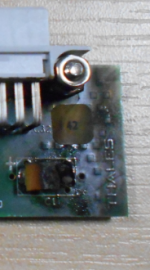
A slightly damaged tantalum bead capacitor:

1711564290718.png

A slightly damaged couple of TTL ICs:

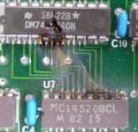
1711564390809.png

Plenty of spares though...

I have suggested to the repair engineer that they check a couple of other ICs - as they are connected directly to the same data bus pins that now provide power from the mains electricity grid!

Dave
 
Back
Top