• Please review our updated Terms and Rules here

Current limited power supplies

falter

Veteran Member
Joined
Jan 22, 2011
Messages
6,620
Location
Vancouver, BC
Something I got lightly rapped on in my video about repairing my KIM-1 was the use of my Amiga power supply as a power source. A few viewers were upset that I wasn't using a current limited bench dc power supply to power it. I've have a stack of A1000 PSUs and had always used it because they work and were available. If I understand how current limiting works, the potential issue is if it's a short on the motherboard, the psu might fry. Is that what they're concerned about? Ruining an A1000 PSU? Or does current limiting protect the device you're powering also? Sorry for my ignorance on this. I should get a bench supply but for some reason never get around to just pulling the trigger on one.
 
It protects the device. If you power a rare piece of hardware and have a short, a beefy PSU with no current limit will make sure every chip gets fried.
 
It protects the device. If you power a rare piece of hardware and have a short, a beefy PSU with no current limit will make sure every chip gets fried.
Well, just the actually shorting one(s); the rest will just see the rail go down unless the PS spikes as it fails in which case devilry may follow. Probably burn up trace(s) a.k.a. "fusible links" connected to shorted components. Burning traces under otherwise OK components can cause side-effects, and are certainly harder to spot and repair. A current-limiting PS probably has an indication of actual current draw which is helpful to know, even if the current limit isn't hit. Dialing up the applied voltage while watching the current draw can spot problems before they go from "problem" to "outright failure".
 
I see current limiting power supplies used in GPU troubleshooting. You inject enough current to find the shorted part (which overheats and is found by touch or a thermal imaging camera) but not enough current to fry anything important. When you have cards with 100's of components you need to get creative to find the short. So, if you know there is a short but don't know where then you use current limiting supplies to find it.

I think the voltage is set, just the max current is dialup up and down as needed. If you have schematics, you can inject voltage into specific areas and see what happens in that circuit.

Would be nice to have a good benchtop current limited supply as they have very clean power.
 
A few years ago, I bought this one and it has served me well. I know it's an "amateur" model. There are lots of reviews out there about the unit. I very much routinely use the current setting when testing things out.

Since your experience was with bringing up a KIM-1, it brought out some old memories. I hope you will allow me a bit of an indulgence.....

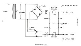
The KIM-1 manual gives this schematic for a suggested power supply.
Power Supply MOS_KIM-1_User_Manual s.jpg

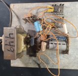
I actually built that to bring up my KIM-1 some 40 years ago (and I am gulping as I post this).
KIM-1 PS 20240515_092443.jpg

I had almost no idea what I was doing back then (some might argue that I still don't). I struggled to understand why there were the two resistors after the diodes and before the regulators (and the 5V regulator would always heat up whether anything was attached or not- which worried me, to say nothing about all that mains exposure). Asking anyone who I could find why they were there, I was told they were current-limiting.

It did work, but eventually I tired of worrying about electrocuting myself and, of course, enclosures were elusive for me to build for reasons that I still don't understand.

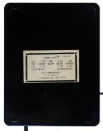
So I bit the bullet and sprung for this KIM-1 power supply of the day from the experts at the Computerist....which I still use today...now I am worried again :)
KIM Power Supply IMG_2739.jpg
 
Thanks guys. So is current limiting similar or same to what you'd be doing with a variac?
No. A Variac will reduce the AC input voltage which for a traditional transformer-bridge-capacitor power supply will simply reduce the DC output voltage proportionately. A short will still cause a large current flow proportional to the AC input voltage. A Variac will either have no effect on a SMPS (for a small reduction in input voltage) or will cause it to shut down completely.
 
Thank you. So how do you choose which tool to use when you are facing a piece of vintage equipment that you suspect hasn't been turned on for a long time? Is it a matter of using one to test power supplies and the other to test the device itself?

Like for example I have a Slicer 186 system I'd love to power up. It has its own power supply.
 
So... I feel like I need to be "that guy" here and suggest that maybe, just maaaybe, that maybe this is (mostly) just YouTube comments being YouTube comments.

The Amiga 1000 power supply is a switching power supply essentially the same as a contemporary vintage PC power supply. Switching power supplies like that (almost always) already have overcurrent protection that'll shut down the supply in the case of a hard short. This is generally pretty fast acting and will prevent the PSU from fully starting if the short is present on power-on. The problem here is if you have a short somwhere "delicate" (say, a short involving a fine PCB trace), IE, something that will burn through if subjected to less current than the max rating of the PSU (it looks like, for instance, that an Amiga 1000 PSU is rated for 8 amps on the +5v feed), you could potentially smoke a trace. Which sure, might suck if you did it to an antique PCB... but it's a lot less likely to happen with a switching power supply than it would be with the linear power supplies most computers used back in the 1970's.

It protects the device. If you power a rare piece of hardware and have a short, a beefy PSU with no current limit will make sure every chip gets fried.

If you have a system with a short from VCC to ground smoking all the chips probably *isn't* going to be a realistic consequence; the current's going to go through the short, not the chips, and blow *that* up.

The thing a current-limiting supply *isn't* going to save you from is if you make a serious mistake and, say, wire the thing up with the polarity reversed. Some chips can be permanently damaged by even a fairly trivial amount of reverse current. You can go ahead and buy the bench power supply that has a big "max current" knob and think you're being "safe" by just slowly turning that knob up, but if you've wired it up backwards all your pretty white ceramic chips will be likely be goners before you see a lot of fireworks.

Honestly the biggest criticism I'd have of using an Amiga 1000 PSU as your go-to bench power supply is old switching PSUs like that usually don't regulate their output voltage reliably unless they have at least a minimal load on them. Some PSUs don't come up at all, while others might give you the wrong voltage; usually an undervolt, but there's still something of a risk there. I use an old Flex-ATX power supply for my bench work, and even though it's from the early 2000s it still has this problem; the 3.3v supply will not regulate accurately unless there's a significant load on it. I've posted this before but here's the photo again of what I came up with to ballast it enough to work properly:

index.php


Yes, that's 16 old incandescent Xmas tree bulbs wired into 8 series pairs.

FWIW, the breakout board with the fuses is something you can find on Amazon for dirt cheap; the fuses add another layer of protection to the ATX supply's built-in short detection. The meter is also an Amazon special (they cost about $10 for five of them) and adds a little bit of extra reassurance that everything is healthy. (I might add meters for every feed if I feel ambitious one of these days.)

Anyway. I'm not saying you *shouldn't* get yourself a nice adjustable current-limiting power supply, but I also think it's fair to point out that having it isn't actually going to keep you from frying an old computer if you make a mistake. And, in fact, I might actually make the case that if it's a PSU that has a confusing interface with multi-modal buttons and knobs it could potentially give you more land mines to step on. It'd kind of suck, for instance, if you accidentally turned up the voltage while intending to up the current limiter when powering something up for the first time...
 
A few thoughts - in a bit of a haphazard order...

I have a fairly cheap dual voltage, isolated bench power supply. I can vary the voltage on each channel, and I have a current indication on each channel PLUS a current limit on each channel.

You would only really use a variac on a linear power supply. Increasing the voltage slowly and monitoring the voltage before and after the voltage regulator(s) and also monitoring the current. Say you have a +5V regulator, as you increase the voltage you should see the input to the regulator increase and then you should start to see the output voltage from the regulator increase. You would monitor this power-up and stop if you were not getting a sensible voltage on the output of the regulator, or you start to get an abnormally high current flow with a low voltage (indicating some sort of short circuit).

You would perform the same test with a bench power supply - but this time bypassing the power supply of the machine (or - for example - feeding your KIM-1). You need to be a bit more careful with machines that require (say) +5V, +12V and -5V (e.g. 4116 DRAM memories) as you need to ensure that the power supplies are sequenced in the correct order to prevent damage. Read the data sheets for the devices to see what the constraints are.

If it is possible to test the [linear] power supply FIRST (disconnected from everything else) - then use car light bulbs as a load. I use a mixture of 6V and 12V lamps of differing wattage ratings. Bring the power supply up slowly (using a Variac) with a small load on each power rail. Monitor voltages and current as you slowly bring up the Variac voltage. Look, feel and smell for signs of trouble. If the output of a voltage regulator starts to get too high a voltage, it could indicate that the voltage regulator is faulty. If this is OK, start to add more load in the form of increasing lamp wattages. I have a bank of very high wattage car headlamps for some power supplies. I also have a bank of very large Wattage resistors on a massive heatsinks with a fan...

I had a couple of +12V regulators on my Cromemco disk power supply units that were short circuit. If I had not adopted this approach - and tested them out of circuit with my bench power supply - I would have damaged my disk drives (as the full +18V or so would have been put directly on the +12V rail of the disk drives)...

Dave
 
Opinions on YouTube are like a-holes. Everyone's got one (even me. 😄)

But I agree with Eudimorphodon.

Things will only draw as much current as they need. You can't really force more current in to something if it doesn't want it (ohms law), so a standard or non-current limited PSU won't damage anything unless it's already faulty. Hooking a 100A PSU up won't force 100A through everything, but if something is shorted, like a cap, or you accidentally bridge two of the wrong pins, then expect some fireworks. Limiting the current can reduce the potential for fireworks - a short will simply drag the voltage down.

A voltage spike is more likely to cause wider damage. Most TTL logic chips will have a recommended operating voltage up to say 5.5V, and an absolute maximum of maybe 7V. The higher you go, the more likely you are to fry multiple things. Curious Marc on YouTube has a series about repairing a bit of vintage HP equipment where the PSU had failed and dumped a high voltage in to the logic circuitry, frying quite a few chips. He built a simple circuit known as a "crowbar" which, upon seeing an out of spec high voltage basically creates a short across the power rail to shut the PSU down by kicking in its over current protection IIRC.
Thank you. Yeah this Amiga PSU I've been using has been great.. it will not start if something is shorted across different voltage rails.

On the other hand I hooked up an old 20mb IDE drive to a current PSU and it lit an actual fire with one of the caps.

I do plan to buy a variac - some of these old linear power supplies are really scary looking and I think that would make me feel a lot safer.
 
Yeah this Amiga PSU I've been using has been great.. it will not start if something is shorted across different voltage rails.

Like I said, my main concern with it is it might not actually be 100% happy if there's not at least some minimal load. Depending on the PSU it's *possible* you might get an out of spec voltage if the thing you have hooked up is drawing too small of a trickle.

If you're up for spending an hour or two tinkering in the garage I'd say just grab some of those little voltmeters (amazon link) and some thumbscrew terminals and slap together something to "formally" convert one of your PSUs into a "proper" ad-hoc bench supply with monitored and labeled outputs. Put the whole thing in an old ammo box or something and cover it with blinkenlights and people don't need to know what's actually inside. I mean... it is actually kind of sketch that you're just inserting the bare ends of wires into the molex connector.

(I mean, sure, that's what I was doing with the Flex ATX power supply until I got the breakout board... well, not just the wires to the thing I was powering, but a loop of wire to activate the power-on function, but I eventually got tired of both the wires falling out and of worrying about explerding something if I made an off by one error stuffing them back in.)
 
Spesking of power supplies requiring a load.. I am wondering if this is what's going on with the Apple Interactive TV thing I have. I tried disconnecting the PSU to test voltages before trying to power up the main board but my DMM shows voltages oscillating between various values at each pin and off. I'm wondering if the PSU is not seeing the load it requires. I'm afraid to connect to the board and find out.
 
Spesking of power supplies requiring a load.. I am wondering if this is what's going on with the Apple Interactive TV thing I have. I tried disconnecting the PSU to test voltages before trying to power up the main board but my DMM shows voltages oscillating between various values at each pin and off. I'm wondering if the PSU is not seeing the load it requires. I'm afraid to connect to the board and find out.
Connect it to a load. I have both a cheap digital load from AliExpress (which is dodgy with PSUs; it's clearly designed only to work with batteries) and a small pile of 50W and 100W power resistors. The latter are fairly cheap and work great: just stick 'em across all the contacts of your PSU, with values appropriate to pull some reasonable amperage within the PSUs limits, and turn it on and see what it does.
 
A few years ago, I bought this one and it has served me well. I know it's an "amateur" model. There are lots of reviews out there about the unit. I very much routinely use the current setting when testing things out.
This, one, right?

1715999264724.png


Actually, that's much closer to a "professional" unit than the MCU-controlled ones with more displays, a huge pile of buttons and a single dial.

Note on yours that you have four dials giving direct fine and coarse control of the voltage and current limiting, and of course indicator lights to show whether it's supplying the requested maximum voltage or requested maximum current. The displays show the voltage and current output at the current time. The only pro feature it's missing is an output on/off switch. (You should never have anything connected to the supply when you turn it on; it wants a moment for the regulation to settle down.)

Amateur supplies look cooler, but are much more of a pain to use since you have to poke at and twiddle buttons to get the knob connected to particular setting, and usually the knob will then disconnect from that setting if you've not rotated it for a bit. And they provide a "watts" output for people who can't multiply two small numbers.

I've got both, and I'll take the former over the latter almost any day.
 
If you have a switched mode PSU (that is not designed to run without a load) you can't really run it without a load and expect to read accurate voltages...

We have some modern switched mode PSUs at work that are designed to run without a load. I still haven't got used to them!

You must assume that a switched mode PSU requires a load to operate correctly. The manual (if you can find it) should specify the minimum load. Again, use a light bulb or power resistor to simulate the requisite load before taking measurements.

Dave
 
I have a little embedded PSU from a router that will produce the right voltages even without load, but it makes a faint squeal and ticking noise when unloaded. As soon as you put even a few 10s of mA on it, it'll settle down.

But it's still a lot quieter than my bench supply so I can leave it running without disturbing me too much.
 
I have a little embedded PSU from a router that will produce the right voltages even without load, but it makes a faint squeal and ticking noise when unloaded. As soon as you put even a few 10s of mA on it, it'll settle down.

I used to have a little PSU like that that came from some kind of network appliance that I honestly can’t remember what was other than it had some kind of telco plug on it along with coaxial Ethernet. (Tore it apart over 20 years ago.) Used it for a while before my current flexATX, but it didn’t actually live that long before dying. Maybe it was bad caps or whatever, but I do wonder if it self destructed because of no-load abuse.
 
Back
Top