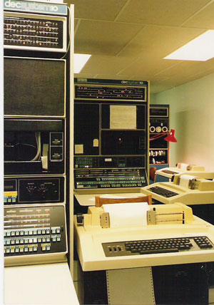
First, I must say it saddens me to think that the KA10 from the University of Queensland's Museum of Computer I.T. may no longer be out there. It was operational in the early 2000's, from what I understood, and was sent to an undisclosed fate by the time the Museum's doors were shut.
- It makes sense that museums in general, would rather have the "ultimate" incarnation of the line, the KL10 - and it is reassuring that several survive.
- It is not unheard of to find a KS10 in private collections.
- I think perhaps the first of the line to go MIA was the KI10 - a disappointing family member that never gained popularity, probably due to it's disappointing performance compared to projections.
- However - the idea that all the KA10s would go extinct, was a surprise to me. If there is one remaining, it seems likely that it's boxed and perhaps forgotten, or unrecognized.
Tim -
I don't want to discourage you, but you do realize what you're undertaking here? If you were able to identify the various parts, it's very likely to be cheaper to buy them individually on the curio market, than to build. Finding an original backplane or frame would indeed be fortunate. I think these would have been 30ga or 28ga Kynar Wire-Wrap [silver] and given the skyrocketing price of metals over the last 10 years, wouldn't expect any to survive unless part of a larger identifiable assembly - or as a relic in a misplaced crate. Maybe one could begin with a few phone calls to Sweden? [I too, heard about that destination]
As for conversation of "multilayer boards" this confuses me. I'm pretty sure the backplanes would be wire-wrapped - not PCBs. Individual boards ~ less certain, but probably double sided G10.
Do we have documentation of
actual boards? I haven't looked - maybe later tonight. I thought I had images, but looking yesterday after your post - I was wrong. (?)
So you'd try to make a system faithful enough to accept genuine boards intermixed with those of your own creation? Am I understanding that correctly?
Picking a KA10 would put you in a pretty reliable family member, except for their power supplies - which were notorious. CompuServe re-designed them completely, making them stone-cold reliable and some 60% more efficient. There are many tales of this still on the internet.
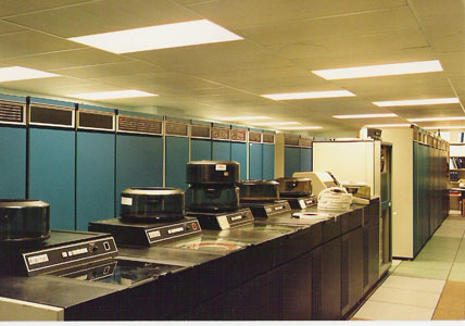
You'll want to consider memory, peripherals and storage before you begin. As Lou points out - original Core memory is not easy or cheap to re-create. Disk drives, MASSBUS and UNIBUS peripherals will also need to be thought out. Some will probably still be obtainable so you might want to begin here and do so before they aren't.
My personal experience at such "collections" is that once you get started, there is a phenomenon of "Critical Mass" which when achieved, causes the effort to
avalanche and get easier thereafter. The important thing is to get going, think ahead, and do a little publicizing along the way. You never know what forces will come to your aid. Even so, I hope you have significant resources to call on for this endeavour, you'll need them.
My advice: Begin with air conditioned real-estate. About half an acre under roof would do nicely. Be sure to include 200 amp 3-phase power. Have a source for a large truck ready at hand - if you run into a system, you'll want to be able to grab it immediately. Keep a passport current.


.jpg")
")