• Please review our updated Terms and Rules here

DOA PETs. (2001-8, 4032 and 8032)

EDIT: Oh, for crying out loud, yes. If I hold a jumper between pin 37 and 38 of C7 the PET still drops to the debugger, but I have a blinking cursor and partial keyboard input. (Some keys don't seem to be responsive, but they could be dirty or there could be a bad connection or... whatever. Time to pull the board and jumper *another* break. Maybe the socket is bad?)

Yes, the 60 Hz timer interrupt comes from C7 pin 37. The PIA is initialized by the processor to cause an interrupt every time the Video On signal pulses at the PIA CB1 input (pin 18 ).

Is there a socket at the C7 PIA? If so, it may have been soldered there with too much heat by a repair person. I wonder how many more bad connections you will find.

Are there any tell tale signs of bad workmanship that can give you clues as to where other bad connection may be? Look for brown spots on the board, etc.
 
And of course, this it the point where you cue me screaming and fighting the urge to drive over the PET with my car.

I pulled the board and discovered that it does seem to be lousy socket. If you give C7 a little extra push it seats. (All the 40 pin chips in this PET are socketed, as are all the ROMs. The sockets don't look like post-manufacture work to me, at least compared to some really hackish soldering in a couple other places in the board, but of course I can't be sure if they're actually stock. Just to note, that 2001 I picked up also had sockets for the same chips. Maybe Commodore shipped socketed boards to repair stations?)

While I had the board out I did a little poking at the keyboard connector to make sure there wasn't any bad connections between it and the chips that drive it (C7 and C9), and then I put the board back in. And the PET is completely dead. Garbage on the screen, and it doesn't even run the tester ROM. (Even if I pull C7 completely back out.)

I've pulled the board back out again, checked for physical shorts/breakages, put it back in and checked voltages and did a few other minimal tests, and haven't found anything obvious except this: Pin 40 reset seems to be stuck low. In fact, while poking around A10 pin 12 (which seems to be the source) I must of touched something that brought it high again because the PET *did* run a few milliseconds worth of the tester ROM (filling the screen with "g"s indicating RAM test pass) before halting again.

I'm really fighting the urge to spew four letter words, so. I think I'd better back off from it for a while before I try to figure out what the (heck) happened. If anyone can help me understand a bit how the power-on reset circuit works that would be great.
 
Last edited:
and haven't found anything obvious except this: Pin 40 reset seems to be stuck low. In fact, while poking around A10 pin 12 (which seems to be the source) I must of touched something that brought it high again because the PET *did* run a few milliseconds worth of the tester ROM (filling the screen with "g"s indicating RAM test pass) before halting again.

It sounds like you have another intermittent signal. The /RESET signal is easy to trace. The source is the 555 timer A2 pin 3 which, based on a RC time constant, outputs a positive pulse for less than a second on power up only. That signal is inverted by A3 and buffered by A10 to give a negative going pulse on the /RESET line to give a clean start for the 6502.

When the /RESET goes high again, the CPU will load a 16 bit address from ROM location FFFC and FFFD into the program counter and start fetching instructions from there.

Hang in there. When you nail the last bad connection, the PET will be solid.
 
Hang in there. When you nail the last bad connection, the PET will be solid.

I still have to be impressed just how hard this thing is fighting to stay dead. Oh well.

I'll trace back from A10 and see where that gets me when I have the chance. Pin 13 on A10 was also low when I checked it last night, and I also verified that the reset line was getting between A10/12 and the CPU, as well as the VIA/PIAs (Pin 34 on them, if I recall.)

There are a couple disk capacitors near the 555 that look pretty sketchy, I wonder if I somehow might of cracked one handling the board and killed the timer circuit. (I haven't exactly been hamfisting the thing around, but those disks do take some pressure when the board is lying face down.) I guess I'll find out.
 
Last edited:
Okay, RESET-ing again...

Okay, RESET-ing again...

So, several days later...

When I came back to the PET it was magically reset-ing again. I've dug into it a little, and I think the failure might of been caused by a temporary short due to, well... sweat on the board. (Yeah, I know, yuck. It was a nice warm day the last time I was working on it, and it's very possible that a drop may of hit it.) So, at least that was easy.

So now I'm back at the debug screen, now with blinking cursor and keyboard input. (See attached screenshot.)

PET_ML_Screen.jpg

I still have a lot of dead keys on the keyboard. I've examined the graphics keyboard matrix here:

http://www.6502.org/users/andre/petindex/keyboards.html

And it looks to me like the dead keys don't really match up into row or column lines, so for the time being I'm operating under the assumption that the problem with them is in the keyboard itself. Is there a good recommendable tutorial out there for disassembling the keyboard to clean/repair it?

Anyway. As the screenshot shows I have access to enough keys to be able to display a chunk of memory around where the PC is stuck when it drops to the debugger, somewhere inside the C000 ROM. And... I think I've found another smoking gun. If I fire up VICE's "xpet", run a "sys 1024" to drop it to the debugger, and display the same chunk of memory I see that on my PET every value in the ROM dump is incremented by 8 relative to VICE . (Except in the instances where the "8" data line would be a one already.)

Looks like I have another bad socket or trace to find.
 
BASIC prompt!

BASIC prompt!

Upon investigation I found the D3 line (Pin 13 on all the ROM sockets) was open between D6 and D7. Thus both the C000 and B000 ROMs would of been corrupted. (I guess I'm lucky the ML monitor is in the D000 ROM.)

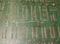
Since the trace is on the component side I just patched it with a jumper on the back:

trace-repairs.jpg

(It's the purple one. The long white one is the one I added earlier to replace the bad write enable line to the "main" 74LS244 data buffers, while that red one in the ROM socket area was already on the PET when I got it. Clearly this system doesn't count as the best example surviving example of Commodore's PCB workmanship.)

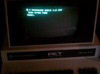
After patching the line I get this:

4k_BASIC_Prompt.jpg

Apparently I have a 4k 4032. Yay!

I think I'll have to get the keyboard working before I can get too much further, as there are too many bad keys to input any meaningful test programs. (Or even load anything.) But still... whee. I've officially made it at least partway, I guess.

On the downer-side... I'm bothered by some of the video artifacts. I'm *sometimes* getting a "phantom cursor" up in the upper left corner (in that 4 byte area with bad characters), and scrolling the screen also seems to cause random wrong characters in a few spots. I suppose it *could* be just a bad memory chip, but the symptoms are strange enough I wouldn't rule out more problems with the video RAM addressing or write circuit. But hey... it wouldn't be fun it it were easy, right?
 
Sounds like you've indeed found another smoking gun; let's hope it's the last one.

The keyboard's another common problem and pretty straightforward. Remove all the little screws to separate the two halves, give the board a good wipe with isopropyl alcohol, methyl hydrate, etc. and wipe all the plunger ends with a Qtip also soaked in the same stuff; I also like to go over all the pads on the pcb with a soft eraser.

Put it back together with just two or three screws and try all the keys before you put all the screws back in, case you have to clean a little more.

Looks like you're really getting somewhere; congratulations!
 
and wipe all the plunger ends with a Qtip also soaked in the same stuff

Mike,
A problem with my keyboard also included the fact that the soft end of the plunger was so old and dry that it was no longer conductive. I used a rubber keypad repair kit which included cleaners, epoxy and conductive paint for a long term fix. But in a pinch, would you agree that rubbing the plunger end with pencil lead would be a help?
-Dave
 
Congrats on making progress.

Yes, a semi-responsive PET keyboard is frustrating.

Mike,
A problem with my keyboard also included the fact that the soft end of the plunger was so old and dry that it was no longer conductive. I used a rubber keypad repair kit which included cleaners, epoxy and conductive paint for a long term fix. But in a pinch, would you agree that rubbing the plunger end with pencil lead would be a help?
-Dave

That helped some, with my original 3032 keyboard but the fix didn't last long. In the end I bought a brand new replacement keyboard off billdeg. The difference was incredible! I could type at full speed without dropping any characters at all.

Tez
 
Tezza...a new photo!!!!

Eudimorphodon, congrats on the fix, you're almost there. Hopefully the artifacting is just a bad RAM.

Phil
 
The keyboard's another common problem and pretty straightforward. Remove all the little screws to separate the two halves, give the board a good wipe with isopropyl alcohol, methyl hydrate, etc. and wipe all the plunger ends with a Qtip also soaked in the same stuff; I also like to go over all the pads on the pcb with a soft eraser.

Put it back together with just two or three screws and try all the keys before you put all the screws back in, case you have to clean a little more.

Thanks. Do I need to worry about springs flying everywhere when the halves are separated, or are the plunger assemblies self-contained?

If cleaning doesn't do it I'm guessing this would be the next thing to try?:

http://sra-solder.com/product.php/6767/94

I'm looking forward to getting the keyboard working well enough to run some test programs to determine why the machine is only seeing about 4k of RAM. It'll be interesting to see if it's "just" a bad RAM chip or another bad circuit causing part of memory to simply not be seen. The amount of free RAM, "3156", is different from the amount of RAM displayed in "xpet" set for 4k (3072), so it's *probably* not another bum address line.

(I am relieved that it seems to be consistant about the amount of RAM, at least. If it was coming up with random numbers I'd worry more about the repair to the memory write circuitry being flakey. Still, though, I should probably cook up some sort of stress test...)
 
Thanks. Do I need to worry about springs flying everywhere when the halves are separated, or are the plunger assemblies self-contained?

If cleaning doesn't do it I'm guessing this would be the next thing to try?:

http://sra-solder.com/product.php/6767/94

E,
No, I don't remember a problem with jumpy springs, but keep the keyboard upside down.

While you are waiting for the keyboard repair kit, rub pencil lead on the end of the plunger to make it conductive again for a quick fix to continue troubleshooting.

To test memory, when the keyboard is working, try to poke and peek memory in that area with test patterns.

poke 3157,170 rem 1010 pattern
? peek (3157)

poke 3157, 85 rem 0101 pattern
? peek (3157)
 
Hi Eudimorphodon!

Long time no see! I'm sorry I've been so scarce lately. Work calls :( But holy cow, it sounds like you've made a ton of progress on your 4032! Congrats!!

For detailed PET keyboard cleaning, this is the method I use (page stolen from Dave Gostelow's GeoCities website, now defunct): http://www.loomcom.com/pet/keyboard/

It is tedious, but it works extremely well. The results are wonderful.

The only caution I have is to be VERY CAREFUL when desoldering and re-soldering the Shift-Lock key. Use as little heat as you possibly can. Too much heat can damage the mechanism. I damaged one of mine and had to disassemble the switch itself and kludge in a fix. Not fun, and ugly.

-Twylo

P.S. See also: http://www.commodorecomputerclub.com/cleaning-a-pet-4032-keyboard/
 
I'm looking forward to getting the keyboard working well enough to run some test programs to determine why the machine is only seeing about 4k of RAM.

If the power-up memory test found a bad location at 3156, it stops testing at that point. The upper 16K RAM may be all right, but one of the lower 16K chips is probably bad.
 
For detailed PET keyboard cleaning, this is the method I use (page stolen from Dave Gostelow's GeoCities website, now defunct): http://www.loomcom.com/pet/keyboard/

It is tedious, but it works extremely well. The results are wonderful.

My goodness Ywylo, most of that work is strictly for cosmetics. To make the keyboard work, it is only necessary to make sure the black carbon tips are conductive. Either with the pencil lead trick as you indicate above or with a "rubber keypad repair kit" which uses conductive paint for a more long term fix.
 
My goodness Twylo, most of that work is strictly for cosmetics. ...

Oh yes, but believe me, in my case extra effort was well worth it. My PET keyboards were literally caked with dust, grime, and in places, a sticky brown mystery fluid. Since Eudimorphodon's PETs came from the same place, I wouldn't be surprised if his are in the same class of filthy.

At that point, doing a deep clean seemed like a no-brainer to me :)
 
If cleaning doesn't do it I'm guessing this would be the next thing to try?:

http://sra-solder.com/product.php/6767/94

Strangely enough I was just looking at this product last night for fixing an Australian computer from 1982 called a Microbee. The $31 shipping fee to Japan is killing me though, so I'm having second thoughts. I'm sure somewhere in Akihabara there is something similar, but asking the right questions and tracking it down the product is going to be very tricky :-(
 
My goodness Ywylo, most of that work is strictly for cosmetics. To make the keyboard work, it is only necessary to make sure the black carbon tips are conductive. Either with the pencil lead trick as you indicate above or with a "rubber keypad repair kit" which uses conductive paint for a more long term fix.
Wow; yeah, that does seem like a lot of unnecessary effort.

Many people just clean a really filthy keyboard by putting it through the dishwasher, being careful not to run it through the high-heat drying cycle.

I guess I've been lucky in that all my PET keyboards have just needed a good cleaning; for those other keyboards whose conductive pads were no longer conductive I've successfully used rear-window defroster repair paint or just glued little aluminum foil disks, depending on how many and what I had on hand at the time. Of course the repair kits mostly intended for remote controls should also work well, but some have been discontinued and they're not always easy to find.

But in any case, as long as you leave the keytops in place nothing will spring or fall out when you remove all the screws.
 
Back
Top