• Please review our updated Terms and Rules here

Faraday A-Tease motherboard

dengelland

Member
Joined
Dec 19, 2008
Messages
47
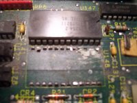
OK, getting closer to unsoldering mc14681 CMOS chip on motherboard due to damage presumably caused by corrosion from leaky batteries.

One dumb question before I begin. And remember this is from someone that is used to dealing with nuts&bolts. Will the new chip need to be (flashed, programed or?) after installed.

Thank You

David
 
mc14681

mc14681

Well, not program per say, but if the computer doesn't have a BIOS based setup, you'll need to run one off of a floppy.
Have you ever desoldered an IC before ?

patscc
 
No I've never changed one before but have always been ready to try something new. Have small soldering gun, lite magnifing glass, desoldering tool, & resin core solder. I do understand its a ticklish operation and i can ruin the mobo, but it isn't working now.

When pc was working and without battery, each time it booted up I had to put in date & time, floppy 1 & 2 and hd 1 & 2. So I presume that will have to be done on 1st boot with new chip & with battery chip will retain setup.

David
 
Driver & Gun

Driver & Gun

You might also need a driver for DOS to recognize the RTC.
I hope it's a small soldering iron, not an actual soldering gun.

Here's a tip that might make your life easier. If you take a small pair of side-cutting wire cutters, you can snip off the ic (since it's shot, who cares ) from it's leads. Then, just gently heat up the pin at the pad, and pull out with a pair of tweezers. Fast and easy on the board.
Personally, I'd solder a socket in first, and then put the clock chip in the socket so I wouldn't have to worry about frying it, but some people don't like sockets. If you need one, RatShack still carries them.
patsc
 
Solder wick

Solder wick

I'd also recommend snipping the leads off of the component if there is no need or chance of salvage. Also use some solder wick when you remove the remnants of the contacts. It's basically a copper braid impregnated with flux. It will pull away the old solder and leave you with clean through holes.
 
A rotary tool, like a dremmel works even better than dykes (it's easy to f*ck up using even the smallest of nippers). You can pick up a cheap one at Harbor Freight for about eight bucks. Just zip through the pins at the body of the chip, then pull the pins with tweezers or mini locking pliers (aka medical forceps, or roachclips, depending on who you talk to).

--T
 
No I've never changed one before but have always been ready to try something new. Have small soldering gun, lite magnifing glass, desoldering tool, & resin core solder. I do understand its a ticklish operation and i can ruin the mobo, but it isn't working now.
David

That's the spirit. Give it a go! You have nothing to lose. I did my first IC replacement about a year ago, and have done a lot since then. It's not that hard, but you do need to take your time and not rush the job. It's exacting work.

I've tended to snip the old IC off with a very small set of snippers, then remove the cut pins one at a time by heating with a soldering iron while pulling with small long nose pliers. When they are all out, process every hole with de-soldering wick until the holes are clean. I've then added a socket and the new chips.

I use a magnifying glass during the whole process.

Some people use different methods but this has worked well for me.

Tez
 
No I've never changed one before but have always been ready to try something new. Have small soldering gun, lite magnifing glass, desoldering tool, & resin core solder. I do understand its a ticklish operation and i can ruin the mobo, but it isn't working now.

Soldering gun? Noooo--a small iron--no more than 30 watts or so is the ticket. Soldering guns are for soldering 12 AWG house wiring and such.

Hope you meant "iron" and not one of these:

61690c8025a7a19e84908a572f1d8120.jpg
 
Corrosion & Chip

Corrosion & Chip

I'm probably pointing out the obvious, but before you put in the new socket or chip, make sure you clean off the corrosion. It's also helpful, after the soldering operation, to remove the left-over rosin flux from the board. Sometimes the residue becomes acidic, causing problems down the road.

Dumb question, but how did you diagnose the IC as faulty to begin with, or was it just corroded so badly that one or more of the pins were damaged ?

patscc
 
Pat, you need to go back over the whole thread to find the story. Basically, the POST was failing when it read the shutdown code after it ran the extended memory diagnostic. The POST code writes the shutdown code, just before the reset, then reads it back afterwards.

Corroded traces were asked about, voltage readings made, etc. The POST code writes the shutdown code, just before the reset, then reads it back afterwards.

I (and several other people) opined that there might be traces under the 146818 that might be corroded also. But the solution is the same no matter what--remove the old chip, check the board traces, put a new chip in.
 
I didn't mean gun as pictured, plan on using radio shack 64GH-150, 15 watt, runs off AA batteries.
I'm old school and an iron to me means the iron in the fire to heat it up, then apply to joint that needs heat. Thats why I said gun. Not that it is shaped like a pistol.
Thanks for reminding me about desoldering braid, have seen it used before but it slipped my mind. Did I read that that is the 2nd or 3rd sign of old age, maybe 1st.
Have & planned on installing a socket.
Had planned on using a desoldering bulb, but will have both handy.

I appreciate all the help

David
 
I'm old school and an iron to me means the iron in the fire to heat it up, then apply to joint that needs heat. Thats why I said gun. Not that it is shaped like a pistol.

David, I'm probably at least as old as you are and can recall the unique sensation resulting from picking up the wrong end of a 100 watt American Beauty soldering iron. Back in the days of point-to-point wiring of tube gear, my Weller soldering gun was a very useful item.

I just wanted to make sure that you were using the right tool for the job. A 15 watt iron sounds like it'll do the job fine.
 
Up Date

Up Date

I've got the old chip out, think I made it without damaging mobo.
Attached see what i found under old chip.
Working nights next week and will reassemble then, taking it slow & easy, checking everything twice.

I want to again thank everyone for all their help.

David


faraday mc146818 chip 008.jpg
 
My goodness, look at the crud under there! I guess we know the problem now.

Good work--just take it slowly and carefully and you'll do fine.

Are you suing a desoldering pump, like a Soldapullt? That's the easy (and fairly safe) way to clear the solder out of those holes.
 
Cats & Flux

Cats & Flux

Good God ! That almost looks like a cat had at it.

I'd brush on a bit of flux to help the solder melt & flow more readily, especially with all that crud there.

patscc
 
Hopfully my soldering is better than my picture taking.

I used a vacuum bulb & copper braid to pull solder out of holes.
Socket is in and looks OK. Trying to decide on which chip, dallas or back with motorola. Have the dallas in hand, ordered motorola with sockets, weren't here in a month so contacted seller and he sent me 5 sockets, but still no chips. ordered another for a dollar.

If someone wants a socket just let me know where to send it (them). Next week should be D-day.

Just for my knowledge, are there sleeves in the holes of the fibre that connect to traces imbedded in the board. There weren't as many visable traces as I had expected.

David
 
board

board

dengelland said... Hopfully my soldering is better than my picture taking.

I hope no one misunderstood my cat comment, it was about the state of the board corrosion, not the picture taking.

dengelland asked...are there sleeves in the holes of the fibre that connect to traces embedded in the board.
Yes. The board is through-plated. It looks to have at least 4 layers, or two layers + ground planes. It might well have more layers, especially if it's a fairly compact board.

patscc
 
Last edited:
I'd stick the Dallas chip in and give it a whirl (without the battery of course--the DS chip has an internal battery). You should at least be able to determine if you can get through the power-on self-test. You can always put the Moto chip in when you get it without having to remove the board, since things are socketed. If the DS chip works okay, you're probably good until you start collecting Social Security.

Just pay attention to which end is which when you put the IC in--and careful not to bend pins on the IC.
 
Finally got back again, had 1 inch ice storm,no power for 1 1/2 weeks and lots of things to do to get machinery operating at work.

Got the MC chip in, looks good to me anyway, no burn on mobo etc.

Got it reassembled and turned it on and didn't get shut down error I had before. But!! it won't boot up (Hopefully I connected something wrong when I reassembled) I get 2 short beeps, then nothing. No video or anything. When I get to work and have time am going to reseat video board.

On the good side I found the manual for the machine, and it should have all information I need, down to all schematics, including the mobo.

Question; under power supply on corner of board is a 2 pin connector that shows to be power test. marked as c142 on board, but j26b on schematis 7 pin out. I think it had 1 wire hooked to it, red from supply, in a 4 pin connector but only 2nd pin in connector used, I have hooked this wire to positive on pin out, does this sound right?

On front panel connector is a 2 pin reset connect, Have reset button hooked to it, the 2 wires from reset switch go in a 4 or 5 pin connector with 3 wires cut off.
3 pin speaker pins are no problem.
5 pin connector for key lock, led etc, has no wire for it or I have lost it.
Key lock switch goes to what looks like a mercury switch to power pc & controls for attached drive unit.
Should there be something on the key lock pins?
 
Back
Top