• Please review our updated Terms and Rules here

Fitment of Blue Lava XT CF card…

Jibbajaba

Experienced Member
Joined
Apr 12, 2007
Messages
190
Location
Davis, CA 95616 USA
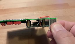
I have this Blue Lava card, but I don’t see how to fit it into my computer. As you can see in the pic, the metal bracket goes at least 1/8” past the PCB, whereas they should be aligned. So there’s no way to get it properly seated in the computer. Is this what BL’s products are like? I bought from them because they seemed to be of higher quality than some of the other stuff out there…95585089-3FFB-4089-9D11-A1949EA60F14.jpeg
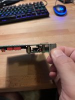
 
As you can see in the pic, the metal bracket goes at least 1/8” past the PCB, whereas they should be aligned.
By my reading of that, you are saying that the main PCB should be touching (or almost touching) the metal bracket.

If so, I even see the gap between the main PCB and metal bracket, in the 'Monotech XT-IDE Deluxe Rev 1.0', shown at [here].
 
By my reading of that, you are saying that the main PCB should be touching (or almost touching) the metal bracket.

If so, I even see the gap between the main PCB and metal bracket, in the 'Monotech XT-IDE Deluxe Rev 1.0', shown at [here].

No, sorry it's hard to explain, but what I'm saying is that if you sight down the card edge connector, you should see the edge of the metal bracket, because on the motherboard each ISA slot is aligned with one side of the cutout in the back of the case. I marked up the image so that maybe it helps me be more clear. the metal bracket on the right should not extend past that green line, but there's that bit sticking out in the red area. But it's not that the bracket is too large, it's that it's shifted over about 1/8" relative to the card. So from the perspective that this pic was taken from, the metal bracket should be shifted down so that the red line is lined up with the green one.BlueLava.jpg
 
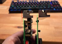
Maybe this is a better picture. Blue Lava card on the left, other ISA card on the right. Looking down from the top. See how on the card on the right, the left edge of the metal bracket is aligned with the PCB? And on the left it's shifted over? So when I put that BL card into the ISA slot, the metal bracket isn't lined up with the cutout in the back of the case, the metal tab on the bottom of the bracket isn't lined up with the little slot in the bottom of the case that it needs to go through, and the screwhole in the top of the bracket isn't lined up with the screwhole in the case. And there's nothing I can do to move it over.
Comparison.jpg
 
The root cause of the problem here is that card uses an off the shelf bulk-produced ide to cf back panel to avoid having to solder the CF card socket or make a custom slot bracket. It’s a cute idea but as your photo shows the offset is wrong if you use a normal female 40 pin PCB mount connector to join them together. In some PC cases this much offset might not be a deal killer because they have sloppier tolerances on the tail piece of the bracket, but… yeah, apparently not with yours.

Only thing I could suggest is loosening the standoff screws holding the two pieces together and seeing if you can tug them apart slightly without breaking the electrical continuity. It’s not a great solution, obviously.
 
Depending on the PC and how the motherboard is secured in the case, You might be able to get a bit of movement by loosening the motherboard screws and re-tighten.

As Eudimorphodon said, It's just a cheap $2 bulk produced Chinese CF adapter, The idea to use those adapters originated from this forum and if done properly it works, But like everything to do with the Original XT-IDE adapters They get copied / modified as cheap as possible and thrown on ebah.
 
The best fix would be to desolder the connector from either the cf adapter or the card itself and sub one with longer tails; shim it while soldering to set the correct offset and you’ll have solved it, but it will be a headache.

(I’ve done this using “double-ended” male pin sets, which are pretty easy to find. For a female connector with long tails you might need a wire-wrap model.)
 
Thanks for the replies and the explanation. Glad to hear I’m not just stupid. I’ve ordered a short IDE extension cable, as then I can just take the CF adapter off of the XT-IDE card and connect them with the cable. This is going into a Tandy 1000 TL/2, which has only 4 ISA slots but still has 5 card cutouts on the back of the case. So the CF adapter can go on the cutout that doesn’t have an ISA slot associated with it,
 
I encountered the same issue with similar Tandy 1000 systems (SL and TL/3). At the risk of sounding lazy, I just cut off the slot tab on the XT-IDE bracket as a workaround.
 
My approach would be to replace the male header on the PCB with one with longer tails and use taller spacers.

Alternatively, start with a blank bracket and put your own holes in it at the proper offset, which, depending on your skills, may be the simplest.
 
I have the same card an have no trouble at all in my Commodore PC20-III or my clone XT.
 
It's a dirty redneck solution but I would guess another way to get enough slop to at least get it into the slot would be to just remove the screws holding the sandwich together on the side closer to the back of the computer and grossly loosen (but you might not have to take them out entirely) the set closer to the plug. Then slightly bend things so they flare apart a little at the back. I'd guess that'd probably give you enough slop to get them in as a "loosely coupled" set.
 
It's a dirty redneck solution but I would guess another way to get enough slop to at least get it into the slot would be to just remove the screws holding the sandwich together on the side closer to the back of the computer and grossly loosen (but you might not have to take them out entirely) the set closer to the plug. Then slightly bend things so they flare apart a little at the back. I'd guess that'd probably give you enough slop to get them in as a "loosely coupled" set.
I took the screws out to test exactly that. You have to pull the two pieces too far apart for this to work. That's how far off it is. Really poor-quality design. Like I said I ordered a short IDE extension cable so that I can just install the two pieces into my computer separately, but frankly it's a bit shocking that I even need to do that. The thing people are telling me to do (use a deeper connector) is what Blue Lava should have done. I shouldn't have to fix someone else's product.
 
The thing people are telling me to do (use a deeper connector) is what Blue Lava should have done. I shouldn't have to fix someone else's product.

Unfortunately there aren't any official qualifications you need to pass to sell stuff like this. :p

I can't remember if it was Blue Lava or another outfit that was selling copies of the Lo-Tech 1MB RAM boards that left off all the bypass capacitors; the only reason why that added up is they didn't understand how to read the schematic and translate it into a parts placement. (If you don't know what bypass caps are and why you'd want them then, sure, how they're represented on a lot of modern schematics is kind of baffling and you might think "why would I bother including that?".)
 
Back
Top