• Please review our updated Terms and Rules here

Fixing up a Hitachi V-509 Oscilloscope

powerlot

Experienced Member
Joined
Nov 20, 2021
Messages
483
Location
Europe
Hi community

After @Hugo Holden had convincing arguments to get one of these scopes and one near me showed up (reasonably priced, plus they're quite rare around here) I decided to try my luck and buy it, under the condition that it shows a trace when turned on.

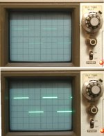
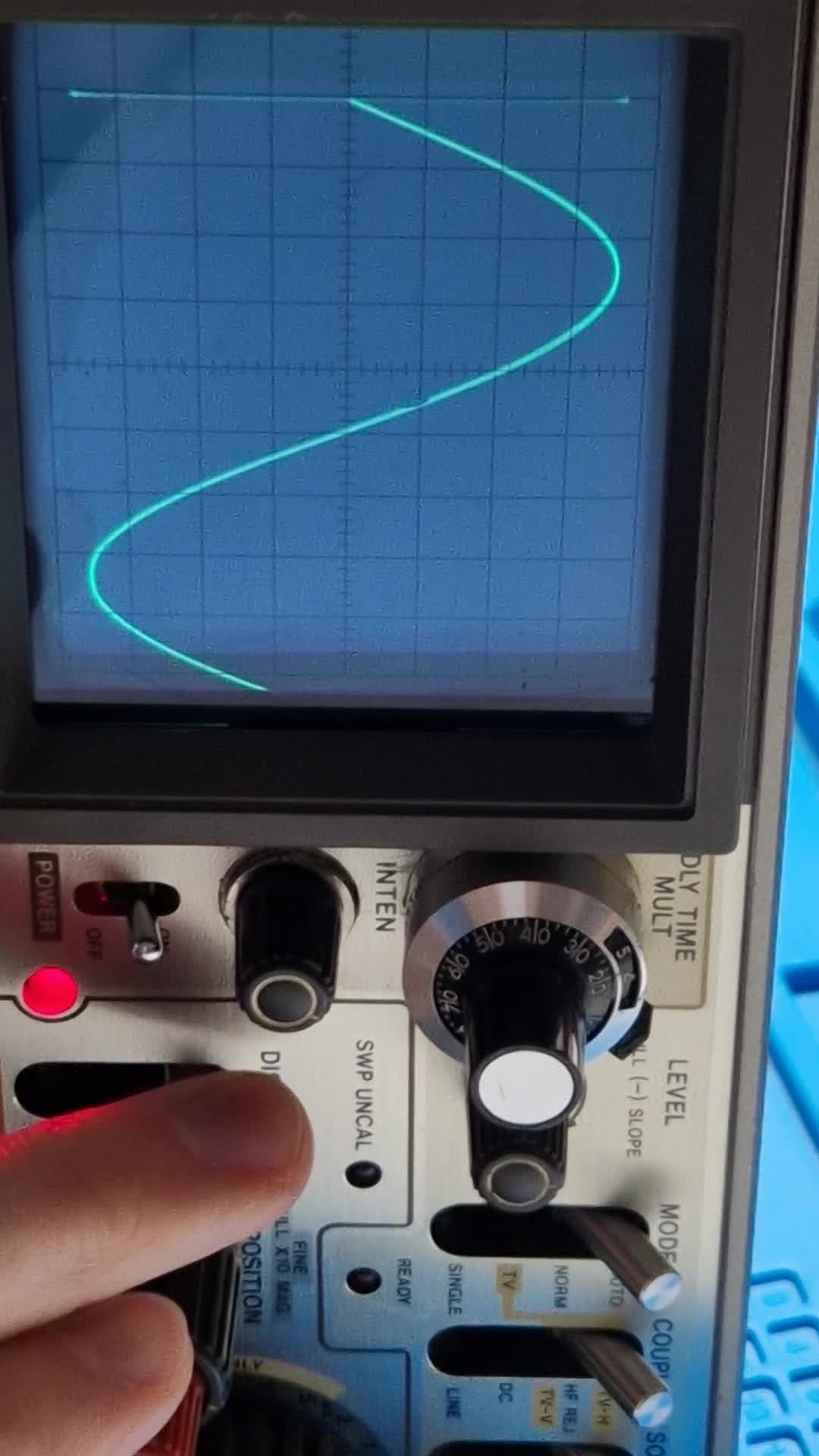
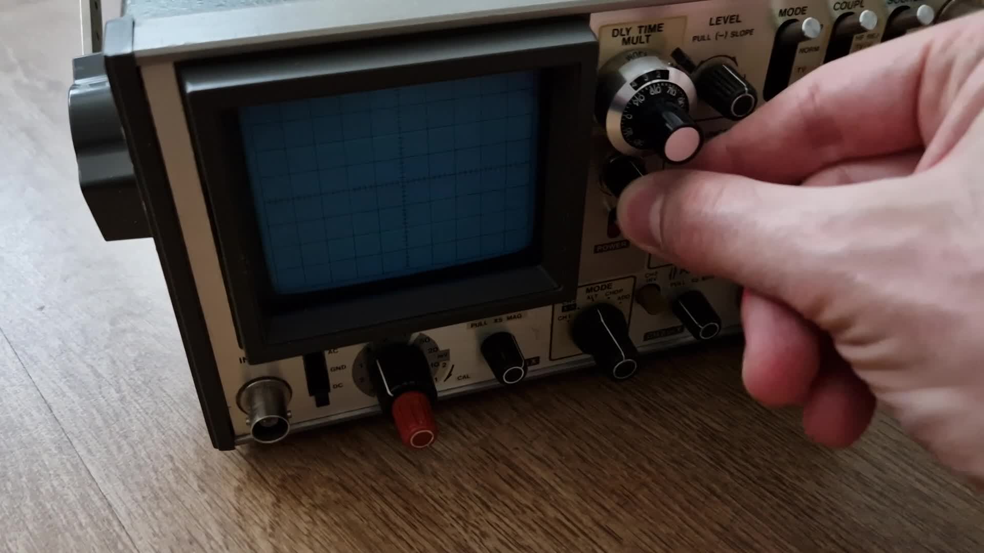
Now, it is pretty banged up, was dirty and it smells like it was in some industrial environment or shop (poor thing). I managed to clean it up and plan to repaint the case, but what bothers me is that in A display mode the intensity needs to be turned up quite a lot for it to show a trace. Otherwise the scope works as it should and is a real joy to handle (I love the haptics and small size).

Regarding troubleshooting: I've downloaded a service manual (https://www.eserviceinfo.com/download.php?fileid=11508) and tested the PSU voltages, which all check out. I fiddled with the CRT gain but it doesn't change the fact that there is a difference in intensity between A and B display mode.

Any advice? I hope it's some out of spec component and not a spent CRT.

Here's a video of the behaviour:

PS: Let me know if this is the right place, or if it's a question better suited for the eevblog forums...
 
The B mode is a bright up mode to highlight the zone selected for the delay time base function. At least the CRT emission in that mode looks good without significant defocus when the CRT beam current increases, that is a good sign for good CRT condition. On the other hand, after power cycling, the beam brightness seems a little slow to warm up again, suggesting the CRT's cathode emission could be a little low. As CRT's age with use, their apparent warm up time increases.

Normally in the A mode the beam brightness a is very bright because these CRT's have a very high final anode voltage for the screen size (10kV...which can support very bright traces even on a 12" sized CRT).

When I get home from work I will check one of my V-509 scopes and the schematic, to see if I can make any suggestions of what to try to figure out if it is an adjustable issue in the brightness control area (there is often a sub-brightness pot in that circuit area) or whether or not it could be the CRT.

These scopes, like any scope, could , in an industrial application be left switched on 24/7 for many years and who knows then how many 1000's of hrs the CRT has on it. Generally when I buy these scopes (since their electronics is so reliable) I go for ones in perfect cosmetic looking order with minimal signs of use. But, they come up less frequently than the banged up ones.

If you can get a good one, it will provide years of trouble free service.

Actually looking at the video again, I am much more confident your CRT has good emission and is ok. The reason is in the moment after it is turned back on, a bright trace flashes up for a moment before it disappears, that would not likely happen with low CRT cathode emission. The brightness control is acting like there might be a leaky filter capacitor in the circuit which is taking a while to alter its charge when the control is manipulated...more tonight.
 
Last edited:
(Sorry about the incorrect remark, the Inten mode is the bright up and the B the B timebase).

The inten mode will always be brighter than A. It is to intensify the delayed window when the B timebase is used to inspect downstream pulses before the switch is moved to B.

Ok, I checked my V509 scope.

In my one the beam in A timebase mode initially appears with about 20 degrees clockwise rotation of the brightness control.

The beam is plenty bright enough with the control set at 50% of its rotation.

If the A timebase is set on 0.5mS/div and the B timebase on 0.2mS there is almost an exact beam brightness match switching between the A & B timebase. (Inten setting in between much brighter)

Of course, if the A or the B is set to run faster the relative brightness drops in that mode.

If the A & B timebase setting have a different relative brightness with those settings, the first thing to check is that each timebase is running at the correct frequency with a test signal. But don't worry if the Inten mode is much brighter than A or B.

There is a CRT bias preset potentiometer RV1021, which will affect the overall brightness, but it won't likely change the relative brightness of the A & B traces, which is dependent on the timebase frequency and the rate that the beam travels across the faceplate.

If you set the brightness control to say 20 degrees rotation in A mode, then set RV1021 to just see the trace appear, I think all will be well.

The operation manual (which also has the schematic) explains on pg 28 explains how to use the A-INTEN-B switch.

(looking through this scope's schematics again, which I have not done much since the mid 1980's as they have been reliable, it reminds me of what a fantastic job Hitachi did making this small scope, I'm just as impressed with it now as I was back then, everything about it is wonderful, the H &V amplifiers, the trigger circuits it is a masterpiece of discrete analog design, with the occasional IC, Tek themselves would have been impressed with it. The fact that these are available for the $100 to $200 region now, is nothing short of a miracle)
 
Last edited:
Hello Hugo

Thanks for measuring your scope for comparison. I'm actually surprised it works this well, given its condition when I unpacked it. Not a single part was changed...

The B mode is a bright up mode to highlight the zone selected for the delay time base function. At least the CRT emission in that mode looks good without significant defocus when the CRT beam current increases, that is a good sign for good CRT condition. On the other hand, after power cycling, the beam brightness seems a little slow to warm up again, suggesting the CRT's cathode emission could be a little low. As CRT's age with use, their apparent warm up time increases.

Normally in the A mode the beam brightness a is very bright because these CRT's have a very high final anode voltage for the screen size (10kV...which can support very bright traces even on a 12" sized CRT).
I couldn't measure the final anode voltage, because my probe doesn't fit through the metal frame.. but it does go out of focus if I overdo it with the brightness (past 3 o'clock position)
When I get home from work I will check one of my V-509 scopes and the schematic, to see if I can make any suggestions of what to try to figure out if it is an adjustable issue in the brightness control area (there is often a sub-brightness pot in that circuit area) or whether or not it could be the CRT.

These scopes, like any scope, could , in an industrial application be left switched on 24/7 for many years and who knows then how many 1000's of hrs the CRT has on it. Generally when I buy these scopes (since their electronics is so reliable) I go for ones in perfect cosmetic looking order with minimal signs of use. But, they come up less frequently than the banged up ones.
I would really like to own a more pristine one, it must be even better... I'll keep looking for one which doesn't have exorbitant prices and/or shipping fees...

(Sorry about the incorrect remark, the Inten mode is the bright up and the B the B timebase).

The inten mode will always be brighter than A. It is to intensify the delayed window when the B timebase is used to inspect downstream pulses before the switch is moved to B.

Ok, I checked my V509 scope.

In my one the beam in A timebase mode initially appears with about 20 degrees clockwise rotation of the brightness control.

The beam is plenty bright enough with the control set at 50% of its rotation.

If the A timebase is set on 0.5mS/div and the B timebase on 0.2mS there is almost an exact beam brightness match switching between the A & B timebase. (Inten setting in between much brighter)

Of course, if the A or the B is set to run faster the relative brightness drops in that mode.

If the A & B timebase setting have a different relative brightness with those settings, the first thing to check is that each timebase is running at the correct frequency with a test signal. But don't worry if the Inten mode is much brighter than A or B.

There is a CRT bias preset potentiometer RV1021, which will affect the overall brightness, but it won't likely change the relative brightness of the A & B traces, which is dependent on the timebase frequency and the rate that the beam travels across the faceplate.

If you set the brightness control to say 20 degrees rotation in A mode, then set RV1021 to just see the trace appear, I think all will be well.

The operation manual (which also has the schematic) explains on pg 28 explains how to use the A-INTEN-B switch.
Unfortunately, I can't get a good result compared to what you're writing. I followed the service manual:
v509-crt-bias.PNG

I darkened the room completely and this is a trace which "just appears" - anything more and the vertical line on the left intensifies and a bit more and it shows a retrace line. I'm at 37 V grid bias voltage at the RV1021 pot at this point.

v509-trace1.jpg

This is at 1ms/div, .5V/div showing a 100Hz sine wave at 3V into 50 Ohms - it's a bit squished on the right side it looks like...

(looking through this scope's schematics again, which I have not done much since the mid 1980's as they have been reliable, it reminds me of what a fantastic job Hitachi did making this small scope, I'm just as impressed with it now as I was back then, everything about it is wonderful, the H &V amplifiers, the trigger circuits it is a masterpiece of discrete analog design, with the occasional IC, Tek themselves would have been impressed with it. The fact that these are available for the $100 to $200 region now, is nothing short of a miracle)
Agreed, I'm also amazed at the "simple" design for a 50 MHz scope with those features and size!!
 
Yes I would go with the manual's setting for RV1021. Probably my scope was set up (rv1021) with the Intensity control a little more anticlockwise than the manual has suggested.

If after this, if the beam cannot be adjusted to a good brightness, without significant defocus, that would suggest an aged CRT.

That vertical line on the left is a little unusual suggesting a problem with the rate of beam flyback or the beam blanking during flyback. I'll check my scope tonight. Almost as the the beam had paused there before the sweep started. Can you tell me the trigger settings you were using ?
 
Last edited:
I took some photos of my V509, the top one is the intensity knob position that gives a dim trace in bright room light ,it is less of a clockwise rotation than the manual suggests, this V509 has never been altered from its factory settings. "A" timebase and just using the probe test signal.

As you can see when the control is just over 50% rotation it is bright. Also I moved the trace right a little to make sure to see the start of the trace on the left. Try setting RV1021 to be like this and check what sort of brightness you get with the inten control at 50% and that way we can effectively compare the CRT's condition.

But, no matter what I did, I could not replicate what you are seeing on the left of your trace, where it appears for a moment on your scope that the scan has stalled for a moment before it starts the trace, creating that vertical line, which is obviously the sine wave signal as it is brighter near the top & bottom of the line and has the same magnitude as your test signal. I cannot think how that could occur as a fault in the scope timebase, but I guess it is possible that a fault in the hold off circuit switching could do this. Can you try another signal from another source (like the scope's test signal) just on the off chance it is actually in the test signal itself.
 

Attachments

  • v509.jpg
    v509.jpg
    69.7 KB · Views: 4
Last edited:
Having once worked in a cal lab, I'm thinking the scope could use a good calibration.
It could do, but I have never had to calibrate either of my V509's, they have stayed well within acceptable limits with aging. Though, if somebody has been inside the scope, tweaking things, then it could be a whole other story.
 
Yes I would go with the manual's setting for RV1021. Probably my scope was set up (rv1021) with the Intensity control a little more anticlockwise than the manual has suggested.

If after this, if the beam cannot be adjusted to a good brightness, without significant defocus, that would suggest an aged CRT.

That vertical line on the left is a little unusual suggesting a problem with the rate of beam flyback or the beam blanking during flyback. I'll check my scope tonight. Almost as the the beam had paused there before the sweep started. Can you tell me the trigger settings you were using ?
I noticed it too.. it only shows up when turning up RV1021 high enough. Trigger settings were all on CAL and the main trigger level in the middle.

When I set the pot to something "reasonable", it disappears:
v509-trace2.jpg
I took some photos of my V509, the top one is the intensity knob position that gives a dim trace in bright room light ,it is less of a clockwise rotation than the manual suggests, this V509 has never been altered from its factory settings. "A" timebase and just using the probe test signal.

As you can see when the control is just over 50% rotation it is bright. Also I moved the trace right a little to make sure to see the start of the trace on the left. Try setting RV1021 to be like this and check what sort of brightness you get with the inten control at 50% and that way we can effectively compare the CRT's condition.
I effectively can't...If I set RV1021 to show somehing that bright at 50% intensity, I already see what I think is a retrace line or some other fault. Also, at this grid bias setting I can't even turn the brightness down anymore, it just defocusses (see next picture).
But, no matter what I did, I could not replicate what you are seeing on the left of your trace, where it appears for a moment on your scope that the scan has stalled for a moment before it starts the trace, creating that vertical line, which is obviously the sine wave signal as it is brighter near the top & bottom of the line and has the same magnitude as your test signal. I cannot think how that could occur as a fault in the scope timebase, but I guess it is possible that a fault in the hold off circuit switching could do this. Can you try another signal from another source (like the scope's test signal) just on the off chance it is actually in the test signal itself.
The test signal shows irregularities as well (my function generator is old, but not that bad):
v509-trace3.jpg
Having once worked in a cal lab, I'm thinking the scope could use a good calibration.
I assume also more than that... but compared to my DSO (the most recently calibrated device I have), it's not too bad and apart from the still slightly distorted right side, probably near or within spec:
v509-cal-signal.png

By the way, I noticed that changing the voltage from 190V-240V on the variable isolation transformer also impacts the brightness of the trace. It is also quite dim when used on the DC supply.
 
Your trace brightness looks basically ok.

There is some issue in the time-base.

To get this effect, I think what is happening is that the sawtooth H scan wave, immediately after flyback, must have a flat spot before the linear ramp starts. That is why you are seeing that bright dot on the left of the trace, which is not normal.

It will be necessary to go into the V509 H scan circuit, and look at the sawtooth wave, with your other scope, to find out what has gone wrong.
 
When I look at the schematics the waves all seem to have flat spots. I will try to find this circuit and compare them to actual readings... if this is the circuit you're referring to?
1663412108620.png

Unfortunately it's a bit illegible... I'll report back when I managed to take the readings
 
Here are the measurements... it does look slightly off, if the the assumption is that the flat part is supposed to be only one divison wide. But I can't recognize at which values it was measured. The Hitachi scope was set to 0.5ms/div and no input signal was given.

v509-h-1-tr829-base.pngv509-h-3-tr828-emitter.pngv509-h-2-tr829-emitter.pngv509-h-4-tr853-emitter.png

If you suspect the wave to be wrong then I would need to check the signals coming from PEF-566, right?
 
There are two possible explanations, either that flat spot is too long, or the CRT's Beam blanking is too short. The beam should be cut off until just fractionally after the trace (the ramp) starts. It might just be a beam blanking failure.

We need to compare the timing of the blanking signal to the flat area at the start.

I'll look at the schematic again.
 
Last edited:
Can you test the scope using the B sweep and see if the issue is on that sweep too ?

looking at the schematic it appears that the CRT beam blanking is fed in as part of the Z axis signal, pin 1 of P901 on the high voltage board. This appears at the collectors of the Z output amplifier (transistors TR908 & TR905), there should be a rectangular wave there that blanks the CRT beam prior to is start.

It is coupled by C1025 into the the CRT's grid. So you can compare that voltage on the collectors, time wise, when it is negative going (as this polarity blanks the beam) to the flat area in the the H deflection waveform, in theory the blanking should either be the same length or a tad longer. But with this fault I think you will see it a tad shorter.

It appears this blanking signal is introduced to the Z signal on the Sweep Generator circuit by IC505 which is listed as a 14053BP , which is a cmos 4053 multiplexer/demultiplexer. It also looks like that is used to modulate the beam intensity on the A sweep ! These Cmos IC's can fail (though having said that the ones in my scope haven't) but that IC could possibly be responsible because it ties together the beam intensity issue on the A sweep, and the blanking timing error, allowing the beam to be seen stopped on the left side of the trace. The two problems are linked to the same part.

So I would look at IC505 very carefully with your other scope at its control & output signals.
 
Last edited:
B Sweep has the the same issue, but the intensity of the unblanked part doesn't change:


The blanking signal seems to be slightly shorter, as you said:

v509-h-5.pngv509-h-6.png
with the intensity turned all the way up:
v509-h-7.png

I would like to measure the 4053 IC, but it's buried within the scope and there's no way to get at the pins without taking everything apart.

I think you're right that there's a possibility the low intensity could be caused by the blanking circuit, but I'm not sure if it's worth to completely disassemble the scope for a slightly out of spec component...

If I can get the board out or at least the pins exposed I'll try, but from having a quick glance it looks rather complicated.
 
It looks like the blanking is normal just prior to the start of beam flyback as it should be and that it un-blanks just a tad too soon, though there is not much in it. Clearly though if the CRT was blanked prior to the start of the trace that defect could not be seen on the left hand side.

Well it is a matter of deciding what to do, if you feel the disassembly is warranted or not to repair this issue.

Though it is a little unusual that a timing event (unblanking) appears to be happening a little sooner than was designed (that is if the blanking pulse is the one that is defective) but the thing is that it is a relative timing issue. Generally, for the most part, faults tend to delay timing in these analog-mixed digital circuits.

This makes me wonder, especially since the leading edge of the blanking pulse looks fine, that there might not be any defect in the blanking pulse at all. And the flat period prior to the start of the linear ramp, for some reason has become a little longer than normal. I think this might be the case, comparing your recordings to the faded ones in the manual ?
 
Generally, for the most part, faults tend to delay timing in these analog-mixed digital circuits.

This makes me wonder, especially since the leading edge of the blanking pulse looks fine, that there might not be any defect in the blanking pulse at all. And the flat period prior to the start of the linear ramp, for some reason has become a little longer than normal. I think this might be the case, comparing your recordings to the faded ones in the manual ?
Agreed, let's assume the ramp signal is wrong (judging from the oscilloscope pictures in the service manual), then the same sweep generator board would still be at fault, no? If I understand correctly, it just takes the two signals from P506 pin 1 + 3 and amplifies them, and one already looks wrong going into the amplifier circuit, when looking at the first picture from #12

Would you mind taking a measurement of the ramp for comparison, to eliminate the possibility that the service manual is inaccurate?

PEF-560 is right under the bottom cover, I have marked the components where I took measurements in cyan (hopefully I got it right):

v509-pef-560-back.jpg
 
Last edited:
Can you advise the sweep time setting you had when you measured the ramp and on that setting with your digital scope measure the amount of time that the ramp is flat & I will compare with my scope
 
At 0.5ms/div on the Hitachi scope, the flat part looks to be 2.2ms wide... I tried to take a more precise measurement, if that helps?

v509-h-8.png
 
Hi,

My results are different which is odd, so check the period.

In my scope, on the 0.5mS/Div timebase rate, the flat part before the ramp is 3.2mS long, the period is about 9.2mS (not about the 8.3mS that your recording suggests on the 0.5mS/Div rage). And, the blanking pulse, as expected, is a tad longer at 3.33 mS.

Maybe something is off with the generalized timebase calibration on your scope.

The first order of the day then, would be to calibrate the timebase (or at least check it). Maybe somebody has been messing with the timebase Cal settings and this has created the disparity between the blanking & timebase timing.
 
Back
Top