• Please review our updated Terms and Rules here

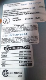
Gateway 2000 486 DX/2 50

I can't vouch for Ebay mystery meat, but I'd recommend looking for DOMs designed for industrial use, which are usually (but can't be guaranteed) to support older PC104 type machines. PC104 is an industrial embedded standard based around the ISA bus, so disk technologies for it tend to cater to the old CHS limitations.

You'll also want to stick with small capacities, like under 1 GB, unless you know the limits of your BIOS's CHS addressing. Some BIOSes had bugs with the CHS routines that would cause erratic behavior if the geometry was too large. One such bug was that one or more of the CHS values were not bounds checked, so you could select a number that would overflow the stack and cause stack smashing.

This can lead to extremely errant behavior, like the BIOS itself crashing, the stack pointer/program counter going off into lala land, or somehow ending up in video memory and having garbage written to the screen. I've experienced all three scenarios.

As for the 40 vs 44 pin, it's just desktop or laptop form factor. Desktop DOMs use 40 pins and need a separate power source, usually via a pigtail with a molex or berg connector. 44 pin IDE provides power via the four additional pins on the connector and doesn't need to be powered externally. 44 pin IDE is used on laptops and embedded devices, you don't want one of these, unless you want to use an adapter.
 
Ok Today was a day of tons of progress.

first off Thanks @GiGaBiTe for suggesting the caps. I had my doubts but ran out of things to try so I recalled the 2 dozen plus SMD caps yesterday evening. It was late when I finished so I didnt test it until this morning.
I fired it up and was now able to get into the system bios.
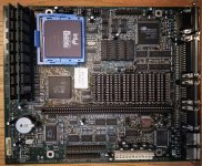
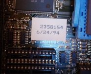
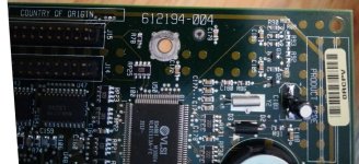
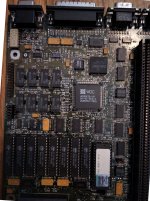
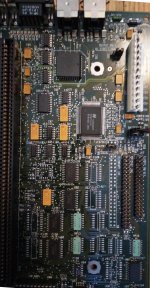
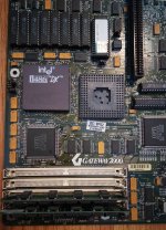
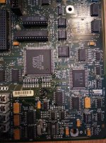
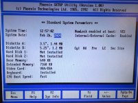
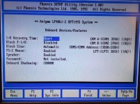
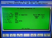
View attachment 1273005View attachment 1273006View attachment 1273007View attachment 1273008

So the original 2X 4MB 72 pin simms give bad ram errors. So I added new ram. As of now I have two 8MB modules in there for a total of 16MB of ram and thats fine for my needs. The 83Mhz intel Pentium overdrive must have a fault as it will only boot intermittantly. The 486 DX 33mhz I installed boots every time. The bios is old, version 1.0 with no IDE auto detection. Does anyone know if the firmware updates have been archived? I sincerely hope so. I connected the original Western Digital Caviar 2340 341MB drive into the bios when I found the sector/track info online. And it booted. It was riddled with errors but no bad sectors. I was able to backup the sony proprietary cdrom drivers [it has a 34 pin SONY CDU33A-GW |(Gateway?)| and matching 8 bit ISA COR334 controller card]. Not really anything else on the drive worth saving sans a mickey mouse memory game. I thought at this point I could reload the OS but I thought, hell I want to run a Compact Flash alternative. And for the life of me I could not get any of my IDE to CF adapters and CF cards to work on this bios! I dont know what it is but I get nothing but bios errors and FDISK sees nothing. So I formatted the old caviar drive and loaded DOS 6.22 and windows 3.11 from a gateway OS cd I have. Problem is that cd has no gateway programs or drivers. I went on archive.org and found ver 1.5 and ver 1.7 gateway restore cds from around 1996 but thats far too recent.

So my next questions is where can I find the actual drivers and original gateway software for this desktop? Where can I find a Bios upgrade?

And how can I add CF card HDD replacements?

I got the etherlink iii it came with working as windows setup took care of that. And since the unit is working I bought a 486 heatsink fan, and gateway keyboard and mouse from ebay.

Oh one last thing. Good news too. I found I had one other sound card in my stash. I bought this card to add to my IBM 5160 but never did. Its an 8Bit ISA Sound Galaxy BX II. Anyone know if there are windows drivers and dos drivers for this thing (saves me from having to buy another expensive sound card.
View attachment 1273010View attachment 1273011
Rather than the CF card why no try a DoM? I've had pretty good luck with both but the DoM is a slam dunk. I put a 32GB DoM similar to this one: https://www.ebay.com/itm/294538516445?hash=item4493dd17dd:g:23EAAOSwkDJhjH9Y
 
Well I bought some generic 1gb DOM. I guess we will have to wait and see. I am curious though. What do I put in for the hard drive specs in this bios!?
 
Some drives have the CHS printed on them, others rely on auto detection. If you can't find it on the module, or the manufacturer's website or elsewhere, you can try fudging numbers to see if it will work with it.
 
So Im still waiting on the DOM. In the meanwhile I started trying XTIDE universal bios on this gateway which has a single IDE connector. The results were very bizarre. If I add an xtide ver 4 card all is well, but if I add an xtide universal bios and use the onboard single ide connector it will not see any of my sd card devices (even though that configuration on my other 486 full tower I am working on sees CF cards via the dtk ide controller). Like I said with the xtide ver 4 card it sees the CF cards fine, just not via the onboard controller.

Can someone explain this? Do I really not have a hold on the whole universal bios config yet or is it the onboard IDE connector is too limited to see it even with XT IDE universal bios?
 
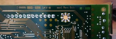
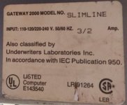
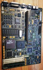
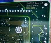
Ok. So why the photos? I mentioned earlier in this thread I bought another 486 gateway desktop computer from @ajacocks which I planned to use to fix my 1994 gateway desktop. This one is a 1992 gateway desktop. Here are the photos for it. Notice the second cpu socket. Is that for a 387 match co processor or is this a 386/486 motherboard?? Also this board has a secondary IDE header that isnt populated and neither are the ICS that support it by the looks of it. I have no been able to find jumper settings for this board online yet:
IMG_20240226_115619.jpgIMG_20240226_115632.jpgIMG_20240226_120319.jpgIMG_20240226_120247.jpgIMG_20240226_120339.jpgIMG_20240226_120346.jpgIMG_20240226_120355.jpgIMG_20240226_120402.jpg


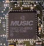
This motherboard doesnt have a sound card but it has this strange chip labeled "MUSIC". Any idea what this is?
IMG_20240226_120544.jpg
 
And just to be thorough here are photos of the bios pages:
IMG_20240226_125732.jpgIMG_20240226_125751.jpgIMG_20240226_125721.jpg


The thing about this 1992 gateway desktop is there are no electrolytic caps, but tantalums which is nice compared to the 1994 system. It doesnt have an onboard battery for the RTC but 3 header pins. I have a cr2023 running to them but this system WILL NOT retain any of its settings. I have no idea why. The date and time are correct in the photo only because I just updated it.


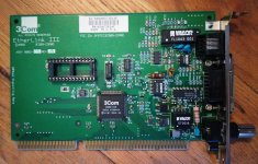
A couple cards it came with were another etherlink III with a boot ROM socket, nice!
IMG_20240226_122757.jpg


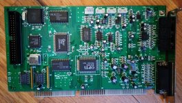
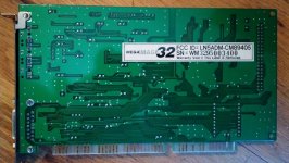
And a 16 bit ISA sound card with CDrom drive header.. Maybe I cant run XTIDE from the etherlink III and get a secondary IDE from the soundcard????
IMG_20240226_122811.jpgIMG_20240226_122852.jpg

Again none of these cards are destined to any machine right now.. Whatever configuration I can achieve and have them working is where they will remain.
 
It doesn't have an onboard battery for the RTC but 3 header pins. I have a cr2023 running to them but this system WILL NOT retain any of its settings. I have no idea why. The date and time are correct in the photo only because I just updated it.
I see that the motherboard in post #28 has an 82C206 chip on it. Amongst other things, that chip contains the real-time-clock and 'CMOS configuration' functionalities. Per [here], the 82C206 usually has a 6V battery providing backup power to it.
 
I see that the motherboard in post #28 has an 82C206 chip on it. Amongst other things, that chip contains the real-time-clock and 'CMOS configuration' functionalities. Per [here], the 82C206 usually has a 6V battery providing backup power to it.
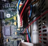
Hmmm.... If thats the case maybe you can help explain these jumpers with voltages. I thought it was setup for 3v to 4.5v and it would be ok. The red and black leads above are running to cr2032 I mentioned.
IMG_20240226_165351.jpg
 
Hmmm.... If thats the case maybe you can help explain these jumpers with voltages. I thought it was setup for 3v to 4.5v and it would be ok.
The datasheet for the 82C206 shows that the 82C206's Vcc pin is allowed to go as high as +6.7V, but I see no spec about the minimum voltage required on that pin for continued RTC/RAM operation.

Yes, the location of J8 (up against J7) together with the annotations for J8, certainly suggest that the J8 jumper must be to allow for various battery voltages.
Without access to the circuit diagram, I have to guess that:
- The {>6.4V} setting introduces a high-value series resistor (or maybe another diode) so as to reduce the voltage reaching the 82C206 ?
- Assuming two diodes-in-series, the {3-4.5V} setting removes one of the diodes ?

Do you measure +3V (probably less due to series diode/s) on the Vcc pin of the 82C206 ?
I will check when I have that machine open again. (y)
 
The datasheet for the 82C206 shows that the 82C206's Vcc pin is allowed to go as high as +6.7V, but I see no spec about the minimum voltage required on that pin for continued RTC/RAM operation.

Yes, the location of J8 (up against J7) together with the annotations for J8, certainly suggest that the J8 jumper must be to allow for various battery voltages.
Without access to the circuit diagram, I have to guess that:
- The {>6.4V} setting introduces a high-value series resistor (or maybe another diode) so as to reduce the voltage reaching the 82C206 ?
- Assuming two diodes-in-series, the {3-4.5V} setting removes one of the diodes ?

Do you measure +3V (probably less due to series diode/s) on the Vcc pin of the 82C206 ?
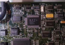
Ok I wanted to make this check before I got wrapped up in other things but the problem is the opti 82c206 is a rectangular package like this one here (smaller IC):
$_57.JPG


But all I can find for the pinout online is the CHIPS version which is a square package. So Im not entirely sure which pin is vcc
 
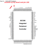
The datasheet for the Opti 82C206 is at [here].
In that, the 'pinout' that you seek is figure 3-2, found on document page 6.
So I am getting no voltage reading at all from the VCC pin.

I took out the jumper below the battery connection and checked for 3v from the pins on the 3-4.5v pin, 6v pin, and 6.4v pin. On the 3-4.5v pin I am getting 0.6v. On the 6v pin I am getting 3.15v, and on the 6.4v pin I am getting practically no reading (0.01v steady).

So either I have the jumper in the wrong location or I need to get 6v from a battery.
 
Last edited:
Ok... chock it up to Im a complete idiot. Looking at the diagram and where the bevel is compared to my IC threw me off completely. My fault.

8c2061.png8c2062.jpg

I put the jumper back in where I originally had it and I can get 3.1V at both VCC pins on the 82c206 powered off. Powered on I get 4.91V from both VCC pins.
 
Back
Top