• Please review our updated Terms and Rules here

Gateway 2000 486 DX/2 50

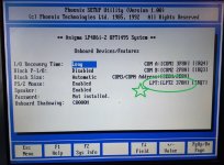
I have a cr2023 running to them but this system WILL NOT retain any of its settings. I have no idea why. The date and time are correct in the photo only because I just updated it.
I put the jumper back in where I originally had it and I can get 3.1V at both VCC pins on the 82c206 powered off. Powered on I get 4.91V from both VCC pins.
And the PSRSTB# pin too (just to be sure) ?

And measuring 3.1V with a CR2032 in place, presumably you have the J8 jumper in the 3-4.5V setting.

Reading the OPTi 82C206 datasheet, I do not see anything like "3-6V operation" for the Vcc pin.
The best that I can find is in section 5.1, that indicating a maximum rating of +6.7V for the Vcc pin.
Could it be that 3.1V is too low for operation of the OPTi 82C206 ?
Do you have the means to connect up a larger voltage battery ?
 
And the PSRSTB# pin too (just to be sure) ?

Ok hold on that one

EDIT::::: 3.12V from pin #7 PSRSTB# with power off.

And measuring 3.1V with a CR2032 in place, presumably you have the J8 jumper in the 3-4.5V setting. 4.9v with power.

Yes that is correct.

Could it be that 3.1V is too low for operation of the OPTi 82C206 ?
Thats where I am leaning right now.

Do you have the means to connect up a larger voltage battery ?
Id really rather now Connect a 9v battery (I may have one measuring 7v which was too low for my multimeter) Im just afraid the current will be too much!
I did order these which should arrive in a couple days: https://www.ebay.com/itm/254628295576
 
I'd really rather now Connect a 9v battery (I may have one measuring 7v which was too low for my multimeter) Im just afraid the current will be too much!
Yeah. You don't know if the '6.4V' setting of J8 is going to reduce the measured-at-7V battery voltage to something below the max. Vcc rating of 6.4V
 
A little something else to mention. I have a small baggie of these laptop RTC battery recplacements. You know, coincell battery in heatshrink with two wires coming out to a tiny connector. Smaller, thinner cell than a cr2032. I figure I might as well use them for something so I took two (still measuring over 3V) and put them in series. When I test the new cells I get 6.2v. When I connect them to this gateway I get 2.5V even if I test at the pins of the battery connection!!! So that wont work. Too old maybe?
 
Smaller, thinner cell than a cr2032. I figure I might as well use them for something so I took two (still measuring over 3V) and put them in series. When I test the new cells I get 6.2v. When I connect them to this gateway I get 2.5V even if I test at the pins of the battery connection!!! So that wont work. Too old maybe?
Some thoughts:
- A poor connection somewhere.
- Bad battery, where it's terminal voltage drops excessively under even a little loading.
- {Unlikely}: Good batteries, but when the J8 jumper is in the 6.4V position, a motherboard fault/mis-design is overloading the batteries.
 
Well the 6v cr2032 batter holders came in. I just made one for my IBM P70 I was also working on and it works fine in that system. Diodes came in today as well. Problem is I am out of CR2032 batteries so I had to order some of those tonite.

So I will post back soon with something to try and tackle this 1992 gateway RTC problem.
 
While waiting for the CR2032 batteries to come in I spent the past two days working on the 1994 gateway 2000. I thought I had a power supply issue as the machine was behaving strangely and locking up. I have been using the lo-tech rom card with XT IDE universal bios to try loading it up and its just not working. I think Im going to use the dip switches on the board and disable the single IDE channel and add a Winbond IDE controller much like I did on my 486 tower.

Im getting really inconsistent results from the onboard IDE, but if I use an XTIDE 8 bit card everything works great.

These two Gateways are kicking my butt.
 
So The batteries came in and I built up another 6v dual cr2032 pack. It came out to 6.5v. I was thinking about the voltage drops I was getting testing before and thought it wasnt necessary to use a diode here as well. I moved the jumper to the 6.4V position and connected the battery up. I measured 4.9V at both VCC pins and the PSRSTB# pin. Same as if power was connected and on. So far its holding the settings so I think we have this problem sorted.

I dont think this explains the different voltage jumper positions at all however. IT only seems to hold the settings above 6V.

On another note I added a rom card with XTIDE universal Bios and this 1992 gateway has no problems with CF card auto-detection from the onboard IDE. Which makes no sense that the 1994 (smaller board) gateway has such an inferior IDE device on the mainboard. Hopefully that IDE controller I bought will resolve that.

Either way I can continue on this 1992 gateway 486 build. That makes two systems down and one to go!
 
I guess I was wrong. I booted up the 1992 486 gateway to test a disk on module that came in the mail and the settings were clear. Makes no sense. The voltage is still good. I dropped the jumper from 6.4v to 6v and added the settings again.
 
So I was able to get my 1gb DOM working on the 1992 onboard IDE with XTIDE universal bios. I tried loading it with my SDLPT device but its acting strangely. I have the motherboard jumper set to LPT Bi-directional. And the strange thing is the blue led for activity on the SDLPT turns on as soon as power is applied to the machine. IF I disconnect the power cable (usb cable) the blue activity light is always on when power is applied. Strange. I set the jumper on the motherboard to output only, same thing. I change the SDLPT driver from SDRIV.sys to SD.sys and move the jumper... same thing. This parallel port is acting strangely.
 
Ok I figured out the parallel port issue on the 1992 gateway 2000 so I can use my SD2LPT...

IMG_20240312_173337.jpg

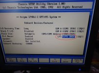
As you can see LPT1 uses a nonstandard address.

If I change it to LPT2 its normal and works great!
IMG_20240312_173755.jpg
 
Back
Top