• Please review our updated Terms and Rules here

Getting Compaq Portable 1 running

Bill-kun

Veteran Member
Joined
Nov 2, 2020
Messages
685
Location
Michigan
Compaq Portable 1, the first computer that Compaq ever made. Previous owner shipped it to me. It's in immaculate condition! No ABS plastic yellowing at all, except on the actual keyboard keys! Not even a thread out of place on the handle! Yet, a mere 4.77 MHz.

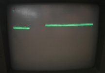
Trying to start it up, the computer makes all the normal sounds I think it should, but the screen only displays one wraparound line of "ááááááááááááááááááááááááááááááááááááááááááááá ". The previous owner said that's what it did for him when he tried powering it up. The unit had previously been in a closet for 10 years. The cursor in the upper left blinks but does not move.

Do I need just a normal 360 kB. MS-DOS 3.20 boot disk, or do I need a 360 kB. Compaq system configuration disk, or diagnostic disk? If so, which one? I don't see one in the Softpaq library that sounds like it was made for the Portable 1.
https://ftp.zx.net.nz/pub/archive/ft...m/pub/softpaq/
http://cwcyrix.duckdns.org/ftp-archi...a/pub/softpaq/

Or it is more likely something like pulling the video card out and reseating it?
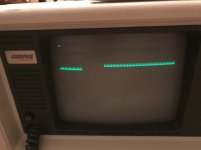
aaaaaaaaaaaaaaaaa - Screenshot 2021-12-22 022926.jpg
 
Last edited by a moderator:
I have the plus model with the hard drive. Prints any failures as numeric codes on power up. Beeps once when trying to boot.

Haven't seen setup disks for this generation machine. Should boot standard DOS 360k floppy. Floppy drive light comes on for a short time during BIOS testing and then back on to boot.

If I don't have a disk in the drive Boot failure gets me diskette error, replace and strike any key when ready. Hitting key will attempt to boot again.

Can't say what causes your screen issue.

Mine had the bad foam disks in the keyboard that I had to replace.
 
A normal Compaq Portable will sit there displaying the blinking cursor in the upper left for a minute while it tests the RAM. Then it should try to boot from the floppy, and if you have one, then the hard drive.

Does yours eventually try to boot the floppy? It should display an error message if no boot disk is found.

That feels like a bad ram chip in the video card. But you should start by opening it up and making sure all cards and chips are seated properly.

A normal vanilla PC/MS-DOS disk will boot on there. It does not require extra software, except a tool that enables/disables a software key click sound on Compaq's DOS. Compaq OEM DOS disks can be found floating around out there.

If it is a bad video ram chip, then the machine should still boot and work but may display some garbage on the screen. Booting and running a diagnostic tool, such as CheckIt, would help narrow things down.

Note that if someone has not already done so, the foam pads in the keyboard key switches will need to be replaced.
 
I somewhat remember having bad ram in mine and socketed it / replaced it.

Also, the keyboards often need to be redone with some new capacitive foams.
 
Note that if someone has not already done so, the foam pads in the keyboard key switches will need to be replaced.

I can at least "press any key to continue" to try booting again from a floppy if it isn't present or isn't a boot floppy. But I can tell they definitely need replacing. Here is the 8-Bit Guy's video on exactly that. Thankfully, he points to a source for modern replacement parts for those pads.
https://www.youtube.com/watch?v=5fju5eRxdRY
Source for modern replacement keypads ($29): https://texelec.com
Another source for modern replacement keypads ($100): http://www.drviragopete.com/keyboard-repair-kit.php
And NCommander's video on the same subject: https://www.youtube.com/watch?v=BZl6RIeinj4

That feels like a bad ram chip in the video card. But you should start by opening it up and making sure all cards and chips are seated properly.
...
If it is a bad video ram chip, then the machine should still boot and work but may display some garbage on the screen. Booting and running a diagnostic tool, such as CheckIt, would help narrow things down.
...
Does yours eventually try to boot the floppy? It should display an error message if no boot disk is found.

The computer makes long-short-short beeps, which indicates a video error. It actually does say "Non-system disk or disk error. Press any key to continue." But the "ááááááááááááááááááááááááááááááááááááááááááááá" is still persistent on the screen when it does. There is no hard drive (although once this is fully functional I plan to add an ISA CF board as a modern hard drive). The left floppy drive does read the boot floppy as if it is booting from it, but the screen does not change after it starts reading it.

I continue to be astounded by the great condition of this unit. Taking off the covers, it looks like it's never been taken apart before. I don't even see a single speck of dust on the inside! If it is a bad video chip, maybe this problem is what caused a past owner to just store it in a closet for years or decades, and that may be why the computer is in such great condition today.

I unseated and reseated the video card and no change. The edge contacts all look perfect.

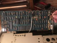
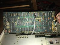
There is only one socketed chip on the video board, the second largest chip, labeled "(C) COMPAQ 1982 / 100519-1 / OKI M3864-04 / JAPAN / 4441". What chip is this? It looked properly seated. I used my iFixit kit to unseat and reseat it. No change. It looks like I will have to learn how to read and make sense of the schematics to use my multimeter to track down the bad chip on the video board.

IMG_8007.jpgIMG_8008.jpg

I have been watching a lot of Adrian's Digital Basement in the past 2 weeks because he does detective work on vintage circuit boards like no one else I've seen. He explains exactly the logic process he is using, why the logic he's using is sound, how to do the testing via multimeter/oscilloscope/chip tester/etc., the conclusions reached, and the video even keeps moving at a good pace. From what I've seen on his fixes, this symptom of mine does sound like either bad chip seating or bad chip.

References:
That last link, at the Sams website, is the only place I can find the schematics at. Their schematics are dated 1987 with the Sams company name/logo. Is this a company that has just studied and made schematics of other companies' electronics for 40 years? Is that legal (in the USA)?
 
Update: The schematics from Sams do not give schematics for the video card, which is what I need. At best there is a photograph which does not match the version in my unit.

The service manual for the Portable 1 does not give schematics either. At best there are diagrams of the video card, pointing out the jumper locations, which do not match the version in my unit.

So now the next two questions are:
  1. How do I find schematics for the VDU card version that I have? Screenshot 2021-12-23 010049.jpg
  2. How do I start checking the chips on the VDU board for being bad? In general, are there specific legs for each chip type that I should check for being shorted to ground?
 
What happens if you hit a key enough that you get to the bottom and the screen scrolls? If the bad contents scroll up and new bad contents appear in the same location I would suspect a memory chip is bad. Since only a little part of the screen is bad I would not expect a short to ground so don't expect checking pins with a DVM will show anything useful. Not booting with a good floppy could be a separate problem or related.

From https://www.ascii-codes.com/ it looks like the character you have on the screen is an 0xa0. A space is 0x20 so 0x80 bit is on when it shouldn't be. Single bit stuck on is reasonable failure mode for memory chip. In that case when the text scrolls through the bad region or error message is printed on that line you should see other strange characters that are the proper text with 0x80 added.

My board has 8 IMS1400 chips for the memory. That's 16kx1 static ram. If you have a scope or logic analyzer when PC is displaying the blank screen the bad chip should show output data looks different (burst of high) than the other chips. If there's other activity on the line it may be hard to see with scope.

Other techniques I've seen people use to find bad chip is to bend leads so they grip well and push a good chip over the suspect with power off then turn on. If the pattern changes on one chip its likely the cause. Look for change and not expect the problem to fully go away.

The other would be to trace memory data pin to known pinout chip or through buffer to edge connector to determine which chip is connected to high data bit. People don't always connect data bits in the labeled order to buffer chips.
 
What happens if you hit a key enough that you get to the bottom and the screen scrolls? If the bad contents scroll up and new bad contents appear in the same location I would suspect a memory chip is bad. Since only a little part of the screen is bad I would not expect a short to ground so don't expect checking pins with a DVM will show anything useful. Not booting with a good floppy could be a separate problem or related.
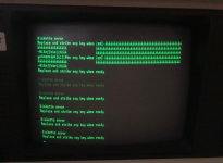
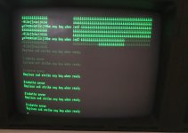
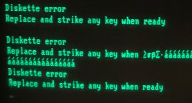
Scrolling the screen results in the following. The characters that look faint are blinking, and you are seeing the afterglow of the green phosphor.
Screenshot 2021-12-24 165048.jpg Screenshot 2021-12-24 165110.jpg

After inserting the boot disk and pressing a key, I get the same original screen. The disk drive sounds like it is properly booting from the disk, but the screen does not change, even after the supposed booting finishes and I press other keys to try to type.
Screenshot 2021-12-24 165124.jpg

From https://www.ascii-codes.com/ it looks like the character you have on the screen is an 0xa0. A space is 0x20 so 0x80 bit is on when it shouldn't be. Single bit stuck on is reasonable failure mode for memory chip. In that case when the text scrolls through the bad region or error message is printed on that line you should see other strange characters that are the proper text with 0x80 added.

I know how to read hexadecimal digits, but can you help me understand the hexadecimal math there? Why is a space relevant? What is it that makes you say 0x80?

Other techniques I've seen people use to find bad chip is to bend leads so they grip well and push a good chip over the suspect with power off then turn on. If the pattern changes on one chip its likely the cause. Look for change and not expect the problem to fully go away.

I've seen Adrian Black do this. I don't have any spare chips to try this. I would have to order one/some, but I'd like to try tracing the problem first.

My board has 8 IMS1400 chips for the memory. That's 16kx1 static ram. If you have a scope or logic analyzer when PC is displaying the blank screen the bad chip should show output data looks different (burst of high) than the other chips. If there's other activity on the line it may be hard to see with scope.
...
The other would be to trace memory data pin to known pinout chip or through buffer to edge connector to determine which chip is connected to high data bit. People don't always connect data bits in the labeled order to buffer chips.

Tracing the problem is what I'd like to do. I don't have a logic analyzer. I have a multimeter, of course. I do have a scope that I can borrow, but keep in mind that I haven't used an oscilloscope in about 20 years, and even then it wasn't much, so I will be learning how to use it all over again.

Since I don't have the schematic for the video board, all I can do is trace stuff on the board using my eyes, a multimeter, and a scope. But I need a walkthrough on how to do that since I don't know IC chips. This is definitely something I want to learn how to do, so how do I start, at least, for this case? In the board picture above, for example, U42 is "(Texas Instruments logo) J419X SN74S374N". What does J419X mean? What does SN74S374N mean? Do I Google "SN74S374N pinout"?
 
I know how to read hexadecimal digits, but can you help me understand the hexadecimal math there? Why is a space relevant? What is it that makes you say 0x80?
Because that tells us which RAM chip on the Compaq video card is bad. If 0010 0000 becomes 1010 0000 then it is the high bit of data bus line D07 that has the problem. So, looking at the schematic, that theoretically should be the hm6167 16k DRAM chip at U29.

However, it should still allow a DOS disk to boot, so there could be an additional problem.
 
For giggles, try putting it into 40 column mode on startup.
There's 2 blocks of DIP switches on the motherboard. One should have all the switches in the OFF position, the other should have varying ON/OFF combinations.
5 should be off, 6 should be on (video mode options), 80x25.
Toggle 5 on, 6 off with the computer off, then power up. See if you get the same result on the screen. It's fairly high up so it may end up in the same block of memory, but it's worth a try to see if it'll get further than it does.

Phil
 
Because that tells us which RAM chip on the Compaq video card is bad. If 0010 0000 becomes 1010 0000 then it is the high bit of data bus line D07 that has the problem. So, looking at the schematic, that theoretically should be the hm6167 16k DRAM chip at U29.

Please help me follow the math more. I think I’m understanding.
Space = 20h = 32d = 00100000b
á = A0h = 160d = 10100000b

Spaces should be where the “á” is (blank screen with no characters), therefore the difference in binary is the first digit being flipped.

Okay, I follow that so far. But how does that equate to data bus line D07?

So, looking at the schematic, that theoretically should be the hm6167 16k DRAM chip at U29.

What schematic of the video card? I wasn’t able to find one. Please give the link.
 
Please help me follow the math more. I think I’m understanding.
Space = 20h = 32d = 00100000b
á = A0h = 160d = 10100000b

Spaces should be where the “á” is (blank screen with no characters), therefore the difference in binary is the first digit being flipped.

Okay, I follow that so far. But how does that equate to data bus line D07?
The common convention for 8 bits is least significant bit (LSB) is D0 and MSB is D7. Other numbering can be used on datasheets/schematics such as D8 to D1 or LSB D7 and MSB D0.


After its booted but no output have you tried typing a command such as DIR and seen if the drive light comes back on?

U42 is "(Texas Instruments logo) J419X SN74S374N". What does J419X mean? What does SN74S374N mean? Do I Google "SN74S374N pinout"?
J419X is some sort of manufacturing code. Likely encodes where and when it was made. Haven't tried to figure out how to decode. The other is the actual part number. SN is TI specific and N is package code. The S in the middle is technology. S is higher speed Shockley logic. 74 is logic family and 374 is particular part in familiy. If searching for the full part doesn't work you can drop the beginning and ending and possibly middle to try to find. Also try datasheet instead of pinout.
 
After its booted but no output have you tried typing a command such as DIR and seen if the drive light comes back on?

I had a small but powerful realization, that I could rewrite AUTOEXEC.BAT on the boot disk, and in particular to use it to run a file to play music on the speaker. Previously the boot disk was waiting for the user to enter the time and date (the computer I normally use that disk on has no CMOS since it has no hard drive). So I've created a new boot disk, writing AUTOEXEC.BAT to simply run COLT45.COM, a music-playing file of about 1400 bytes from Pianoman from the mid-1980s. COLT45 stops playing if the user types a key. The music played, but the screen stayed the same with character 160. By using that, I can now tell a couple things.
  1. The floppy A-drive, processor, and speaker all work fine. It is only the video that is messed up. In fact, other than the video (and keyboard pads) the computer works fine.
  2. The Enter key does not presently work. There is only one Enter key on this keyboard. So while I cannot enter any commands via keyboard, I can use AUTOEXEC.BAT to run them.
For giggles, try putting it into 40 column mode on startup.
There's 2 blocks of DIP switches on the motherboard. One should have all the switches in the OFF position, the other should have varying ON/OFF combinations.
5 should be off, 6 should be on (video mode options), 80x25.
Toggle 5 on, 6 off with the computer off, then power up. See if you get the same result on the screen. It's fairly high up so it may end up in the same block of memory, but it's worth a try to see if it'll get further than it does.
The mode for 40 columns worked, but only as expected. The same character came up, and otherwise the screen stayed the same.

The common convention for 8 bits is least significant bit (LSB) is D0 and MSB is D7. Other numbering can be used on datasheets/schematics such as D8 to D1 or LSB D7 and MSB D0.
I could use a good introductory video on how to understand vintage computer circuit boards. (That is, not how a PCB is manufactured, not what capacitors and resistors are, but how and why the network of and between the microchips on the board is designed.) For example, is there a "master chip" on this video board that the the D0 to D8 chips are subordinate to? What other subordinate chips are there? What are the subordinate chips' function(s)? I guess this is what the datasheet for the video card is for, if I had it.

J419X is some sort of manufacturing code. Likely encodes where and when it was made. Haven't tried to figure out how to decode. The other is the actual part number. SN is TI specific and N is package code. The S in the middle is technology. S is higher speed Shockley logic. 74 is logic family and 374 is particular part in familiy. If searching for the full part doesn't work you can drop the beginning and ending and possibly middle to try to find. Also try datasheet instead of pinout.
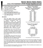
I Googled "SN74S374N pinout" and came up with these successive links which led me to the official TI datasheet at the last link:
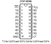
(The datasheet is 32 pages long! Woah!) So now I have the datasheet and I need to learn how to read it. Here are a couple screenshots that seem good starting points for this. It looks like there are 2 data bus lines numbered 1D to 8D and 1Q to 8Q, so I want either 8D which is pin 18 or 8Q which is pin 19. Obviously I have to measure them with the power switch on. Do I have to measure each pin relative to the IC ground, or could I use any ground point in the computer I want to use?
1640548509995.png1640548774784.png1640549384516.png

Unfortunately, unless I missed it, I don't see a table for pinout descriptions. If you do, please point it out.

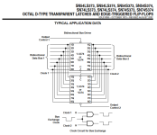
Questions about the third diagram in particular.
  • Why is there an upper half and a lower half? Are these two joined networks in the one chip?
  • Why are there 2 different bus sets, D and Q? Since they are "noded together," are they duplicates of each other, or are they independent?
  • The bottom-most section shows a bus exchange clock and has on-off graphs. What is the significance of this?
Other resources I found:
  • Really good: Starting to learn how to read an IC datasheet.
  • Importance of certain sections of an IC datasheet (a bit higher-level than where I am, but since I am used to reading specs for automotive engineering, I can grasp it).
 
I could use a good introductory video on how to understand vintage computer circuit boards.
I learned this long ago so don't have good current information to recommend.. Could try searching for digital logic design. The IBM PC technical reference gives some information on how CGA graphics boards work and schematics for their card. The Compaq will be implemented somewhat different but will function similar.

Obviously I have to measure them with the power switch on. Do I have to measure each pin relative to the IC ground, or could I use any ground point in the computer I want to use?
For this level of troubleshooting of are we getting high when should be low you can consider all grounds the same to use as the reference. To accurately see waveform edge shape you need a short ground path otherwise you will get overshoot and ringing. More of a problem with newer higher speed logic.

Unfortunately, unless I missed it, I don't see a table for pinout descriptions. If you do, please point it out.
Pages 3 and 4 show the pin function. The function table shows you what happens to output with changes to input. All the Q outputs function the same. Page 4 is a schematic symbol representation. Simple chips frequently present the information this way instead of a table. Did your datasheet video go over this?
Questions about the third diagram in particular.
  • Why is there an upper half and a lower half? Are these two joined networks in the one chip?
  • Why are there 2 different bus sets, D and Q? Since they are "noded together," are they duplicates of each other, or are they independent?
  • The bottom-most section shows a bus exchange clock and has on-off graphs. What is the significance of this?
If you note at the top it says typical application data. This is showing you how to use two of the chips to make a bidirectional interface using the output control lines to set the direction by turning off the outputs of one of the chips. Q is output so you need one chip with Q pointing in each direction.

Wires "noded together," are physically wired together.

Not sure what they are trying to do with the clock. Just seems to be generating two buffered copies of bus exchange clock. The graphs just show the function.


For example, is there a "master chip" on this video board that the the D0 to D8 chips are subordinate to? What other subordinate chips are there? What are the subordinate chips' function(s)? I guess this is what the datasheet for the video card is for, if I had it.
The 6845 is the master chip for video generation but not for the entire card function. Their is a bunch of control logic implemented in the smaller chips which implements the PC bus and other logic needed to make the card work. This era cards normally didn't have one highly integrated chip doing all the control.
 
djg:
Page 4 is a schematic symbol representation. Simple chips frequently present the information this way instead of a table. Did your datasheet video go over this?
No, it didn't. I know logic from math, but I don't know the symbology, nor do I know the correspondence to electrical circuits.

SomeGuy:
If 0010 0000 becomes 1010 0000 then it is the high bit of data bus line D07 that has the problem. So, looking at the schematic, that theoretically should be the hm6167 16k DRAM chip at U29.

Measuring U29 with the power on and the screen being as observed so far. Putting the multimeter on VDC, the black lead on the GND pin, and the red on the others, the readings are:

4.37 VDC, constant, for 8Q
5.01 VDC, constant, for 8D

Does this verify the suspicion that chip U29 is bad?

SomeGuy, please give the link to the VDU board schematic you were talking about. Thanks!
 
Last edited:
I've sent a copy to you via direct message since I can't find the original source I got it from.

Typically just measuring voltage from a DRAM chip does not tell much. Frequently such a failure does not even prevent the entire RAM chip from working - only certain memory cells in that chip may be affected. In that case, outwardly the interface logic voltage and wave forms may seem perfectly normal.

Am I understanding this right that the computer boots from a floppy, but there is NO change to the video output as it boots? Could you set your boot disk to intentionally output some text in autoexec.bat, such as "ABCDEF...".
 
I've sent a copy to you via direct message since I can't find the original source I got it from.
Ah, yes, that one I already have. Reading schematics is pretty new to me, though. Which page has the VDU board?

Typically just measuring voltage from a DRAM chip does not tell much. Frequently such a failure does not even prevent the entire RAM chip from working - only certain memory cells in that chip may be affected. In that case, outwardly the interface logic voltage and wave forms may seem perfectly normal.
So what you mean is that I now need an oscilloscope, to see a graph of the voltage that is much more fine in the time domain than my multimeter can provide?

Am I understanding this right that the computer boots from a floppy, but there is NO change to the video output as it boots? Could you set your boot disk to intentionally output some text in autoexec.bat, such as "ABCDEF...".
Correct, there is no change in the video output. The same "á" characters stay in the same place. The program screen does not appear; only the music starts playing.

I rewrote AUTOEXEC.BAT to fill the screen with equal signs. I tested the new boot on my Epson Apex 1 and it worked fine, loading each line from the disk, one by one. So that "pulse" from the disk drive was also a positive indicator. The Portable 1 booted with the disk, and the "pulse" from the disk drive was there too. But the monitor screen did not change at all from either the non-error boot or from however many instances of "Non-system disk or disk error" messages I made it give by not having the disk inserted.

Here is another photograph of the screen during the boot session in the previous paragraph. It may help in more diagnosis. The system overwrites the word "ready" and "mixed" with "á" we get different characters.
Screenshot 2021-12-27 235221.jpg

The characters are transformed to:
r -- greater than or equal to
e -- lowercase sigma
a -- lowercase beta
d -- uppercase sigma
y -- dot product symbol

I don't find any of the above 5 characters in the 256-character ASCII table. And I know I encountered them in vintage days, like when playing ZZT. But what are their codes so I can do back-calculations in binary to see if leads to other chips on the video card?
 
Last edited:
So what you mean is that I now need an oscilloscope, to see a graph of the voltage that is much more fine in the time domain than my multimeter can provide?
What I am telling you is that voltages and oscilloscopes won't show you squat. It will look like the chip is working normally.

I'm a tad worried about how it is not displaying anything when DOS boots. It could just be software poking in to memory to determine the video card type and getting confused due to the bad RAM, but it could be something more serious.

What I would do at this point is set up a boot disk with the command "CTTY COM1" in the autoexec.bat and connect another computer running a terminal program to COM port 1 using a null-modem cable. (Your machine does have a serial port, right?). That will let you remotely control DOS. Then run debug and manually poke directly to the CGA memory addresses to make sure things are really responding. I have a suspicion that the bytes that do not have the last bit set to 1 are getting it set to 0 instead. So a command like "e b800:0000 FF" followed by "d b800:0000" might return "7F"

But that is probably more than you need to worry about. Replace that RAM chip and see if that fixes both problems.

BTW, those other odd characters are just the last bit getting set on each byte, just like the spaces.
 
Back
Top