Did you see my link from earlier? From https://www.ascii-codes.com/ it looks like the character you have on the screen is an 0xa0.
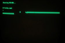
BTW, those other odd characters are just the last bit getting set on each byte, just like the spaces.
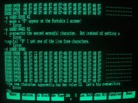
Yes, I did see that link from earlier. I was trying to determine what kind of binary math was going on such that the 5 new characters were the resultants. I thought that might give more info to diagnose. My first confusion is that none of the 5 new characters appear on the 256-character ASCII table, therefore how do I find out their binary values? My second confusion is that, if none of them are in the ASCII table, then how are they characters existing in the computer and on the screen at all, especially when I've seen and used them in vintage programs like ZZT?
What I am telling you is that voltages and oscilloscopes won't show you squat. It will look like the chip is working normally.
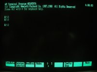
I'm a tad worried about how it is not displaying anything when DOS boots. It could just be software poking in to memory to determine the video card type and getting confused due to the bad RAM, but it could be something more serious.
What I would do at this point is set up a boot disk with the command "CTTY COM1" in the autoexec.bat and connect another computer running a terminal program to COM port 1 using a null-modem cable. (Your machine does have a serial port, right?). That will let you remotely control DOS. Then run debug and manually poke directly to the CGA memory addresses to make sure things are really responding. I have a suspicion that the bytes that do not have the last bit set to 1 are getting it set to 0 instead. So a command like "e b800:0000 FF" followed by "d b800:0000" might return "7F"
But that is probably more than you need to worry about. Replace that RAM chip and see if that fixes both problems.
Getting into the via terminal and using DEBUG is actually a really great idea! And until now I never knew there was a direct DOS command to transfer control to a null-modem-type terminal! My Portable 1 has a 25-pin parallel port. There is no native serial port. But I do have an I/O card I added to my Apex 1 that adds a 25-pin serial port, and I could try transferring that. I'd like to try using the parallel port first, though, if I can.
Do I have to use a null modem serial cable for this, or do I use a normal serial/parallel cable?

Ctty Command
Ctty command information for MS-DOS and the Windows command line. Page includes ctty command availability, syntax, and examples.
Available MS-DOS devices for CTTY
AUX
COM1
COM2
COM3
COM4
CON
LPT1
LPT2
LPT3
NUL
Here is a link I found that tells the ranges of memory occupied by different stuff in DOS.
After the BIOS transfers control to boot sector, the first megabyte of memory looks like this:
Address Size Name 0x0000:0x0000 1024 bytes Interrupt Vector Table 0x0040:0x0000 256 bytes BIOS Data Area 0x0050:0x0000 ? Free memory 0x07C0:0x0000 512 bytes Boot sector code 0x07E0:0x0000 ? Free memory 0xA000:0x0000 64 Kb Graphics Video Memory 0xB000:0x0000 32 Kb Monochrome Text Video Memory 0xB800:0x0000 32 Kb Color Text Video Memory 0xC000:0x0000 256 Kb1 ROM Code Memory 0xFFFF:0x0000 16 bytes More BIOS data
Here is a video by LateBlt ("late blight") on using DEBUG. This is on running BIOS interrupt routines, but except for the memory locations, I think this is suitable as a tutorial for me.
Last edited: