• Please review our updated Terms and Rules here

HardMPU <working title>, anyone here an EE?

ab0tj

Experienced Member
Joined
Mar 4, 2015
Messages
110
Location
Colorado, USA
Hi all,

Since it seems to be almost impossible to find a real MPU-401 or compatible, I am going to attempt to create my own. Once the design is complete, the hardware and software will be open source so others can build them. I am also going to try to offer boards and/or kits for sale (but NOT trying to make a profit). My goal is to port the most excellent SoftMPU software to a PIC chip.

I was wondering if some of you technically inclined people can check over my preliminary schematic and offer ideas and corrections. I know, it's somewhat messy at this point, but hopefully you can sort it out. Let me know if you have questions.

Thanks!

EDIT: File uploaded waaay to small, try here: http://postimg.org/image/o0keu6ukr/
 
Been following your thread over at vogons (where I use a different login name) with interest but haven't participated so far because I had nothing to add. My only comment at this point would be: make sure the pic you choose has enough processing power for the project at hand. You don't want to get into the testing stage to realize you're falling behind the host data rate.
 
Glad to know there's interest. I've been (im)patiently awaiting parts so I can try and get this started.
 
I am interested, because I recently realized I have no MIDI-capable interface on any pre-286 computers, and prices of original equipment are sky-high and going up. I'm always for replacing old hardware with modern functional equivalents. Sustainable.
 
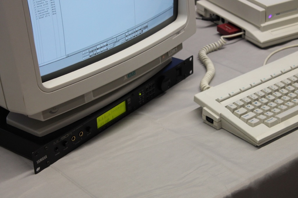
I think it needs a lot of effort to make something like an MPU401 which also sounds good and is fully compatible with all effects like example Yamaha GX standard. I have solved this different. I bough a Yamaha MU90R rack synthesizer. But I mostly use it with my ATARIs.

1900-7a333734.jpg
 
I'm also interested, but my contribution is null... (a part from testing it).

However, I'll find useful for my (poor) soldering skill to have all throught-hole component, if they esist...
 
MPU-401 was a MIDI interface made by Roland on the 1980s for a variety of computer systems, which became a de facto interface. It wasn't based on PIC, which I don't think even existed at the time. According to several sources (http://www.vogons.org/viewtopic.php?t=39594&p=361262 , http://ps-2.kev009.com/ohlandl/sound/MPU-401_Tech_Manual.pdf - contains schematic, http://www.datasheetarchive.com/dlmain/Databooks-5/Document2182.pdf ) it was based on a Hitachi HD6801 microcontroller. Good luck finding any today.

More info at https://en.wikipedia.org/wiki/MPU-401

Also, Arduinos are not based on Microchip PIC microcontrollers but on Atmel's AVR. And the newer generation are ARM.
 
I still have an issue with "PIC". What, exactly does that mean?

For example, the PIC24 and PIC32 families bear no resemblance to one another and none to the 8 bit PICs. The PIC32 is basically a somewhat stripped-down MIPS R4000 CPU with peripherals. The PIC24 is a MPU optimized for DSP uses with a 16-bit register file and 32-bit addressing. The 8-bit PICs generally follow the original 1975 1600-series I/O controller.
 
Between input from Vogons and some things I noticed, many things were fixed since that previous schematic. A new one is here.
 
I'm an EE. Among my various titles is "digital design engineer" so I'll look over the schematics this weekend. I saved them for later.

During lunch I looked up the MPU-401... midi device.

I know someone that did a product like that in the 90s, and he always did PIC designs to a fault. I haven't talked to the guy in 20 years and don't know what became of him; he would be good to talk to if he's still around. I won't mention his name unless I find him online.

There was an ungifted company in Oklahoma City, named Phi-Tech that among their late 80s technology offerings, a midi product was included. I think that company only does contract production today; a once-boss of mine went to work for them for a short term back around '87.

Any particular reason for choosing a PIC micro? If sustainability is your goal *and if* the MPU-401 wasn't a PIC and you're crossing it to another micro, consider one that has market appeal now so its sure to be available later. If MPU-401 was a PIC... fine. I'm no fan of the Arduino processor but its a fixture of hobby-world and so it should be considered as a compatibility portal with whatever the MPU-401 is.

I read another post saying your design (posted elsewhere) has need to maintain pace with external communications... put those sort of details down to help assess the design.

I assume you want to do it as a Through-hole board with lots of dual-in-line packages and 5Vdc. I might be able to help with the layout too, though I use Pads for schematic and pcb layout, I can tell from your schematic you use what I would call and Orcad/Eagle type package.

At 3.3Vdc and surface mount technology, you get a lot more cool options. Don't dismiss that hobbyist-unfriendly path without some consideration.
Thank you. Any input is appreciated. I chose the PIC mainly because I already have programming tools for it. I would not be opposed to using something else if it fit the design better. An AVR (Arduino processor) would fit probably just as well, but I made sure to choose a PIC that is a current production item so it should not be going anywhere soon. And keeping pace should not be an issue now that I moved to using latches instead of attempting to have the PIC interface with the bus directly. The original MPU401 used a processor running at around 1MHz, so a 10MIPS PIC should not have an issue here even after adding software features.

Yes, this would be a through-hole design, to keep it accessible to those who wish to make their own or build it from a kit. I'd love to replace all that 74xx logic with a PAL/GAL/CPLD/whatever, but I have basically zero experience using those. And 3.3v stuff would make the design more complicated since this will be on the ISA bus which is all 5v logic.

I am indeed using Eagle for this. I will look into Pads, as the free version of Eagle doesn't let you design boards large enough for this project.
 
Last edited:
I still have an issue with "PIC". What, exactly does that mean?

For example, the PIC24 and PIC32 families bear no resemblance to one another and none to the 8 bit PICs. The PIC32 is basically a somewhat stripped-down MIPS R4000 CPU with peripherals. The PIC24 is a MPU optimized for DSP uses with a 16-bit register file and 32-bit addressing. The 8-bit PICs generally follow the original 1975 1600-series I/O controller.

PIC18F2620. So, yes, 8-bit. But running at a much higher clock speed than the original MPU401 CPU. The software will be ported from SoftMPU which is mostly C code that was ported from the DosBox project. I will not be attempting to run the original MPU401 software.
 
I have also given thought to using an Atmel Atmega 1284P to develop the software. Then move to a smaller version Atmega once the code's flash/RAM requirements are known.
 
Well, if you want to stay with Microchip and DIP, take a look at the PIC32MX1xx and PIC322xx chips. 32-bit, generous SRAM and 50MHz. 5V tolerant inputs.
 
Yep, just a protocol converter. Sits on the ISA bus (usually at address 330h) and does MIDI (31250 baud current loop) I/O. Many ISA sound cards included so-called "UART" MPU-401 compatibility, but some older DOS games relied on MPU-401 "intelligent" mode for music, which is what I'm trying to include here. It will do both UART and intelligent mode operation. Intelligent mode offloaded some things from the computer like timing and sequencing. The original MPU-401 ran at something like 1 MHz, so a 20 MHz AVR should have no trouble at all replicating the functions. However, the ISA bus runs at 8+ MHz and would expect data to be read from or written to the bus within a few bus clock cycles. I'm not sure even at 20 MIPS the micro could keep up with the bus. The PIC needs 4 clocks per instruction, so 10 MIPS there.

Seeing as how the AVR chip runs roughly twice the instructions per second and has more RAM, I think I will go that route. I have an even newer schematic where I included JTAG for debugging if you'd like to look at that one. Sorry the schematic is such a mess, once I figure all this out I'll redo it to make it look pretty :)

These docs have been invaluable in figuring this stuff out.
MPU-401 Technical Manual: http://ps-2.kev009.com/ohlandl/sound/MPU-401_Tech_Manual.pdf
MIF-IPC-A (interface card for the MPU-401 box) Service Notes: http://www.symphoniae.com/synth/Roland/MPU401/MIF_ServiceNotes_2nd.pdf
SoftMPU (software MPU-401 emulator) source code: http://bjt42.github.io/softmpu/
 
Last edited:
I might be able to help with the board layout on weekends using my CAD and supply gerber print files for making printed circuit boards... depends on how busy I am. Pro bono; no charge. Just for fun. Thru-hole is easy in Pads and I miss the fun of it.
Thanks again for the willingness to help! I must admit, I'm working within my "comfort zone" on this so far, which doesn't really include neat things like CPLDs and 3.3v micro controllers just yet.
 
It looks like the 1-MHZ 6801 is dealing with the 8-MHZ bus by having the data first latched in a LS245, then processed by the HD61J22IF bus interface (whose datasheet I cannot find anywhere)


BTW I have found a disassembly listing of the MPU-401 ROM, dunno if it would be helpful in understanding the timings and dataflow.
Unfortunately the 245 is just a buffer, not a latch. I'm pretty sure that HD chip ("custom bus interface LSI") does latching for the original MPU. I had originally drawn up a schematic based on just the 245, but I'm pretty sure the bus cycle would be over before the microcontroller even jumped into its ISR to handle incoming data from the bus.

Disassembly of the original source might indeed be helpful. More documentation is always good.
 
It's true, 245 is buffer not latch. Guess it's all up to the 61j221f to manage the bus.

Here's the ROM. It's 6801 assembly of course.
 

Attachments

  • roland_6801v0b55p.zip
    19.2 KB · Views: 3
Last edited:
I'll get the datasheets on the PIC and AVR you're considering and see if it can respond to an interrupt quick enough to bypass that TTL glue. Might just need an address decoder to filter out IDE bus activity so the micro only gets tagged when its being addressed. The micro may be able to drive the bus but it would likely need a bidirectional driver to keep the bus timing right; i.e. you don't want you IDE data out to linger when the IDE is doing other things.
Check out the schematic for the interface card from the original MPU401: http://postimg.org/image/o5zfghua9/ - I had originally set up a schematic based on this, with all the signals on the right hooked up to the MCU. That is, until I read that the MPU401 box itself had more bus interface logic in it. After looking at the timings, I'm doubtful that the MCU even at 20 MIPS would be quick enough, but I'm definitely interested to hear what you have to say about it. Oh, and just so we're on the same page, this would be on the ISA bus, not IDE. (When you say IDE, I think of the one for attaching hard drives, so it may just be a difference in terminology.) ISA bus timings can be found here: http://home.mit.bme.hu/~feher/MSC_RA/External_Bus/isa_timing.pdf

I've been reading through the midi.org information; interesting.

I understand about your programming task to synthesize intelligent mode for the older systems that rely on it. I detect that you're leaning toward the AVR so I'll prioritize that over the PIC when I'm looking at it.

The rom dump and disassembly is interesting. Not part of my task though. I'm just hardware and that's the easy part.
After all the reading I've done on the subject, it seems that (for me) the software will be the easy part. I already have some AVR C source written up that should be able to do the MPU401 "UART mode". All it really does is run a loop that shuffles data from the ports into buffers, and then out the appropriate port (ISA or MIDI). This is, of course, dependent on the current circuit that latches data in/out of the ISA bus until the MCU is ready to deal with it, and automatically keeps the host computer informed of if the MCU is ready for more data or not.

I just did a quick disassembler for the 8051 in an excel spreadsheet as an experiment. Later I'll use that technique on some other micros I see. But as you already have the 6801 disassembly, less work for me. :)

Don't worry about the schematics... I studied drafting long before I studied electronics. I can read most anything, including some impossible coiled spring designs a Texas Instruments mechanical engineer sent me back in the 70s. (He drew it like a hurricane symbol but the wires don't come out of a bent shaped coil that way). :)
Glad to hear you can decipher that schematic. Here's yet another one where I added JTAG for in-circuit debugging of the MCU: http://postimg.org/image/n9pc608xz/ I think I will pick up an Atmel programmer/debugger to make life easier.
 
Back
Top