• Please review our updated Terms and Rules here

Help on monitor issue with Taxan 770 plus, powers on but video collapses.

lowlytech

Experienced Member
Joined
May 17, 2018
Messages
103
Location
Oklahoma
So this is a hard lesson to not recap things that aren't broke. I recapped my 1987 working Taxan 770 monitor and when I put it back together I had one high voltage crack on power on. Thinking it was just the anode cap getting settled back or something dusty in and around the cap. The monitor seemed to be powering up with no more HV cracks, I hooked a CGA/EGA signal to it and all I get is a blank screen. Now when I turn it on you can hear a high pitch whine when connected to a signal, and when you unplug the signal the whine does stop, but the screen stays black. There is heater glow when the screen is dark. I took it all back apart and don't see any physical damage anywhere and I went over the caps for polarity again and don't see anything that just stands out to me.

Anyone know where to focus on when the screen comes on for a split second then seems to collapse inward from the right and left sides? I uploaded a short video to my google drive what it is doing..


Thanks so much for any help and suggestions on what to focus on to find the fault. During the recap I tested all caps and ESR's. I hate to say it, but all the caps that came out of the monitor were all in spec. Pretty sick I messed this monitor up.

Thanks...
20231127_190121.jpg
20231127_190120.jpg
20231127_185437.jpg
20231127_181830.jpg
20231127_181826.jpg
 
Unfortunately there is a lot of nonsense on the internet about doing things like re-capping VDU's and other things like discharging the CRT, when it is unnecessary and can lead to a lot of trouble.

On the capacitor issue, generally most radial electros are pretty long lasting unless near heat sinks, especially ones in signal circuits. The only electros that should be targeted for replacements are the surface mount parts as they are terrible and leak, dry out or both. Or perhaps a capacitor which fails an in circuit ESR test or is obviously in trouble with a domed top.

In any case, onto the topic of CRT discharges, or discharges that can occur from the CRT's anode connection to ground, either naturally with contamination around the EHT cap, or if the EHT peaks too high, or deliberately when a person shorts out the stored charge in the CRT bulb. It is a recipe for disaster.

(from the safety perspective it is not required unless the anode cap needs removing, typically to replace the CRT or remove the flyback, for most VDU's, provided the access is reasonable, the cap is better left connected, the stored charge is safely inside the CRT bulb, it cannot escape unless you go under the cap. If it is to be discharged, it should be done with an EHT probe which contains a very high value resistor, with a high voltage withstand spec, typically these resistors, inside the probe, are in the 100M to 1G Ohms, this limits the initial discharge current to a low value)

The CRT bulb's internal and external Aquadag forms the plates of a capacitor and the CRT bulb glass the dielectric. For a CRT of this size the capacitance can be in the range of 2000pF at least. When charged to the order of 21kV or thereabouts the stored energy is in the order of (CV^2/2) or 0.44 Joules. That is not enough to harm a person with a shock, only enough for a significant fright. However a discharge (either intentional or accidental, even to some random earth point) can do substantial damage to semiconductor devices in the set.

If a 2000pF capacitor (which is what the CRT bulb is) charged to 21kV is shorted out with a wire, the initial peak current is horrific. It is only limited by the inductance of the wire, its resistance and the the spark plasma. The spark occurs before the wire touches the discharge point, because the spark gap firing distance in free air is typically around 1000v/mm, so the spark will jump at easily over 1cm for 20kV. The spark plasma as an electrical entity, tends to drop a constant voltage of around 500V in air and has a negative resistance. So as the current increases the plasma gets thicker. The net effect is that the spark itself doesn't help limit the initial peak discharge current of many thousands of amps. If the CRT gets discharged with a wire, depending on the chosen earth point, or even to the CRT's external Aquadag, there is a large current impulse injected into the earthing system, often into the the pcb tracks and components.

This is why , if a CRT is to be discharged, it should be done with the EHT voltage probe with at least 100M Ohms resistance, to limit the initial discharge current to say 21000/100,000,000 or about 0.2 mA.

In the early days, of tube TV's technicians would draw an arc from the EHT with the set running and judge the length of it, the EHT value. When this was tried in transistor sets, many of the transistors died. It prompted Sony, in about 1962, to advise not to allow arcs in transistor sets from the EHT terminal. It seems though that later generations of technicians who like to make youtube videos know nothing about this problem.

I think in this case, either the turn on voltage crack you heard, or perhaps if you discharged the CRT with a wire, (or maybe you had a very large value high voltage rated resistor, like ones in EHT probes) I'm not sure if you did, but this direct short is also what the many defective youtube videos suggest along with global recapping, has likely been responsible for some semiconductor damage in the set, though there could be other causes.

After all that, what about your set now and what does the video show and what can we do about it?

The video shows that the H and V scan starts up, and is running long enough to power the CRT's EHT and run it briefly. Then the H scan shuts down. (While it could be the main psu shutting down, it looks less likely because there was a full H scan shut down but the vertical scan momentarily at least remained preserved).

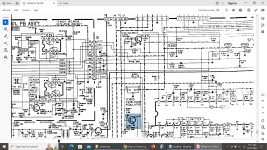
In any set where the EHT runs over around 17kV, there is always the opportunity for X-ray production as the electron energy becomes high enough. In color TV's and VDU's which run the EHT In the range of 20 to 25kV there is normally an EHT over-voltage detection circuit, or at least a feedback control circuit to regulate the EHT, to protect from excessive X-Ray production. Pin 9 on the HA11235 IC is the X-ray protector input pin, driven by the OP amp.

When the EHT gets excessive, it shuts down the drive to the H scan circuitry. I think this is what is happening after you power it up. The fact that you also initially heard a discharge (crack) suggests that possibly the EHT had climbed higher than normal value too.

What I would suggest is checking your re-capping work in the region of the OP amp that detects the EHT value (see attached). It could also be that the discharge/s damaged the OP amp and it may require replacing.

(I'm not sure how much disassembly you did, to do the re-cap, but check the earth connection to the CRT's external Aquadag too, for example if that gets disconnected and the CRT discharges a plasma can jump from that onto some nearby pcb location also check that the earth wire exiting the EHT multiplier/focus & screen voltage assembly is properly connected)
 

Attachments

  • Shutdown.jpg
    Shutdown.jpg
    377.1 KB · Views: 14
Last edited:
Thank you so much Hugo for taking the time with all the explanations of everything. I will focus on the areas you highlighted and get back later today when I get back home. Yes on the disassembly, it was totally taken apart to clean everything as well, but tried to take pictures of every single connector and how everything went. These older multisync monitors are surprising complex with wires and boards going everywhere. Almost like a puzzle putting everything back. Probably had about 5 different shield cages that all had to come off to get to the PCB's and most of the screws are indeed all different lengths.
 
It is a more complicated VDU than usual, being a multi-standard type. The good news is that the service manual looks good.
 
Since it was working, and it still briefly produces a raster, I doubt there's anything seriously wrong. Most likely, you made a mistake somewhere along the way. The problem is you now have a needle in a haystack. When replacing lots of parts, it's a good idea to check that it still works periodically. Recap just the power supply, then test, recap the video section, then test, recap the vertical section, then test...

I would look very closely for solder bridges, improperly installed parts, connectors that aren't plugged in, or are plugged into the wrong socket, and check that you used the right value capacitors. It's easy to accidentally put a 47uF in when it was actually a 0.47uF with a hard to see decimal point. Also, while not common, it's not unheard of for the polarity markings on the board to be wrong for a cap or two. I always note how the original was installed just in case.
 
Just wanted to post an update to say I haven't had a chance really this week to sit down and put the monitor back together. I have seen one cap that the schematic shows is installed wrong, but the PCB shows otherwise so probably a mistake in the service manual. Have found a few solder balls and stuff under magnification, but nothing that looked bridged. Will hopefully have a chance to power it back on tomorrow and see if anything is different.
 
I have seen one cap that the schematic shows is installed wrong, but the PCB shows otherwise so probably a mistake in the service manual.
I wouldn't just assume that the solder mask is correct; those get screwed up too. Maybe less often, but it happens. If the schematic makes sense with the given polarization then IMO there's good reason to believe it. (Who ya gonna believe, physics or yer lyin eyes?) Which is why it's a very good idea to check/record orientation before removing polarized capacitors. Mark the PCB if it isn't already (and correctly!) marked.
 
Occasionally also you will see an electrolytic cap reverse installed at a factory by mistake. The problem in a low energy application might not show up for years. The main thing to check is the schematic, it will often (not always) give the clue as to which way round a polarized capacitor should be installed.

One other trick to watch out for is that in negative rail power supplies, the + terminal of the electrolytics connects to ground.

Commodore did something "interesting" in their 9" VDU in the PET. They arranged all of the electrolytic caps, including ones where the + connected to ground, on the pcb, so that the negative of every electrolytic faced in the same physical direction on the board. This meant they had to go to a lot of extra trouble with the pcb's track design. But it is really obvious if any electro is installed backwards at a glance.
 
Well got the monitor put back together, took about 3 hours to get everything put back and triple checked all the connectors polarities, and ground connections with photos I took before tearing it down the first time. Same exact fault as before. Going to assume that crack I heard must have been a component going.
 
Well got the monitor put back together, took about 3 hours to get everything put back and triple checked all the connectors polarities, and ground connections with photos I took before tearing it down the first time. Same exact fault as before. Going to assume that crack I heard must have been a component going.
Unlikely, most components (though there are a few exceptions) die quietly. The crack was likely a high voltage discharge, that may have damaged a component that then died quietly.
 
Gotcha. So you think the most likely component to swap out first is the IC1404 if all other passives around that measure in spec?
 
It's either shutting down for a good reason such as excessive HV, or there's a problem with the shutdown circuit.
 
It's either shutting down for a good reason such as excessive HV, or there's a problem with the shutdown circuit.
Yes I agree these are the two possibilities.

If the output stage is working normally and the drive voltage to the output transistor has the correct frequency and duty cycle, and the tuning capacitors which help determine the flyback peak voltage are normal, and the B+ supply to the output stage is normal ,then the peak flyback and EHT voltage will be normal, so the fault likely would be in the shut down circuit itself.

But, in the other case, the shut down circuit could be normal and working as intended and one of the three factors above is abnormal. Lets look at the factors one by one:

1)Looking at the drive voltage to the output transistor, if the device is held on for too long per cycle, it stores more energy in the inductances of the yoke and flyback transformer core at the end of scan, because the peak scan current (and scan width is too high). The stored energy is proportional to the square of the current. When this energy is transferred to the electric field of the self & tuning capacitances half way through the resonant process of flyback, the voltage peak and EHT is higher. One clue, is if the raster scan is about the right width, just before shutdown, can help eliminate that as a cause (as well as eliminate the high B+ problem).

2)The current in the yoke and flyback rises at a rate of V/L amps per second, where V is the B+ voltage and L the inductance of flyback transformer and yoke, on the R side of the raster, after the H output transistor is switched on. So if the B+ supply voltage to the H output stage is too high, even with the correct frequency & duty cycle of the drive voltage to the H output transistor being ok, the current (and scan width) and EHT will rise over normal for this reason, so the B+ supply voltage needs to be checked. As noted above, if prior to shut down the width looks ok, this is unlikely a cause.

3)Since the relation between the energy stored in a capacitor E and its terminal voltage is CV^2/2 if you deliver some amount of energy to a capacitor, the voltage across the capacitor's terminal's V, is inversely proportional to the square root of the capacitor value = Root (2E/C). So that if a tuning capacitor on the primary circuit of the flyback transformer goes open circuit, or low uF value, the flyback and EHT can peak over normal for that reason. This can be a spontaneous failure mode in any VDU. Often the tuning capacitors were special quality parts to help prevent failure and production of X-rays (in sets that didn't have X-Ray shut down systems) and you often see on schematics a "!" inside a triangle on their value on a schematic.

I cannot make out the value of these capacitor/s on the schematic as the copy is too poor, However the main tuning capacitor is on the collector of the output transistor in parallel with the damper diode to ground. There is an additional pair of capacitors in series too, in parallel with that main one. These can also be checked for their values. Notice they all have the triangle symbol.
 
Last edited:
Sorry for my absence. Work and the kids have kept me pretty occupied. Have a few days off work this week and thought I would try to get back to this CRT.

I measured the B voltage and something isn't right. I adjusted the pot and tried both directions, to the far counterclockwise (where it almost was from the factory setting) it starts up at 140`150 volts, and far clockwise starts up at around 108volts, however after about 2 seconds you hear the HV kick in and this voltage starts ramping up very fast. It jumps from 108 to 135 then to 150ish within a second, I didn't leave it on longer than a split second once it hit the 150's. The manual says to set it to 126v. Does this help narrow down anything that the B voltage is out of spec?
 

Attachments

  • 20231226_125046.jpg
    20231226_125046.jpg
    1.4 MB · Views: 1
  • 20231226_125243.jpg
    20231226_125243.jpg
    1.6 MB · Views: 1
Seems that transistor Q501 may be bad. I used this website to check with a multimeter


All variations of probing the C1959 on diode mode showed OL except positive on collector and negative on base which seems backwards from a typical NPN transistor. I don't have any spare c1959 to compare.

None of that information is very helpful at all, helping people to help you.

I cannot even find Q501 and it does not seem relevant to an unstable B+.

It does not help that the posted schematic preciously is poor resolution, see if you can hunt down a better one.

Still it leaves the person trying to help you having to download the entire manual again, go hunting through the pages, to check the schematic and find the parts you are talking about or the sub-circuit of interest.

If there is a concern about the stability of the B+ which could very well be your problem if it is unstable, and the voltage going up to high at times (this would trigger the X-ray shutdown system) then you need to find that schematic section yourself, and post it with your question. Otherwise most people might give up helping.

I have cut the page out & posted it (because it is Christmas), and as you can see from it, the +125 V rail (red star added to the diagram), although it has a pass transistor it does not appear from this schematic at least to have a regulating device like a zener in its base circuit.

This means that the voltage here is controlled by the duty cycle of the drive to the base of the main driver transistors, this is Q1906 & 1905 probably, but the scan is too poor to be sure of that number, so I put a blue star near the transistor 1906. These two transistors drive the primary of the transformer on pin 2. Obviously it requires that the output voltage from the bridge rectifier is stable in pin 1.

The duty cycle is determined by the error amplifier IC 1901. It compares the output of the transformer to a reference in negative feedback loop to stabilize the +125V rail. If the B+ is jumping around and not stable at 125V, this does not suggest a problem with a transistor anywhere. More likely a faulty part like a resistor,bad capacitor, bad connection or a faulty pot setting the B+ or something else upsetting the value of the reference voltage or the feedback loop and causing IC1901 to randomly alter the duty cycle.

Initially try cleaning the voltage adjust potentiometer ( I assume when you said "adjusted the POT" that is the nearly impossible to read R1920 on the schematic, never assume your helpers are mind readers), while rotating it 5 or ten times. Then see if you can get a stable 125V setting.
 

Attachments

  • schematic1.jpg
    schematic1.jpg
    283 KB · Views: 8
Last edited:
Thanks for the additional leads. I checked the POT (R1920)and hooked it to a multimeter. It does smoothly go up and down without any erratic jumps. The low end is 0.14k and the high end is 5.9k. I will check the resistors and caps in this same area and report back.


Thank you again Hugo for your time, help and your patience with this. I think the service manual adds a 1 infront of all items compared to what is printed on the PCB, so q1501 is going to be what I am referencing. I only explored this as it was very close to a dumb mistake I had made. I didn't know until I went back and looked at my pictures, but Some component leads had gotten stuck to the bottom of the PCB from flux I assume and totally missed them during first reassembly and power on when I got the first electric crack. Looks like transistor q1501 was the closest thing that potentially could have been shorted, but it may be nothing. Another thing I noticed is even though the Service Manual shows 770+ which is my model, the later pages are for a 775 model and that seems to be all of the schematics. It does look similar enough, so maybe this is how it was suppose to be.
 

Attachments

  • 20231227_092505.jpg
    20231227_092505.jpg
    3.5 MB · Views: 5
  • 20231127_190117.jpg
    20231127_190117.jpg
    3 MB · Views: 7
  • 20231227_092304.jpg
    20231227_092304.jpg
    2.8 MB · Views: 7
  • 20231227_092308.jpg
    20231227_092308.jpg
    2.6 MB · Views: 7
  • taxan q501.png
    taxan q501.png
    272.1 KB · Views: 6
Last edited:
The basic problem to sort out initially is: is the 125V power supply output stable or not ? because you have seen it bouncing around. Or is it responding to transiently changing loads due to a fault (likely in the H deflection system) and not compensating for that ?

The power supply needs to be checked into a dummy load on the 125V output. I don't think any of the other supply outputs require loading for the test.

The question then is what load ? We don't know the proportion of power from the supply's other outputs, so we don't want to put the full load just on the 125V output.

Look at the power consumption of the VDU, P in watts, it should be on the rear panel, or get it from the manual.

I'd suggest using maybe 15 to 20 % of that value as a trial load applied to the 125V rail. So the load resistor could be (125)^2/0.2P = R Ohms and have a power rating of 0.2P or higher.

There is no real need to fully load it for the initial trial to see if the output is stable when it is running independently of the VDU.

This supply should run independently of the VDU, except that there is an input to pin 2 to the IC's internal oscillator, via some series capacitors, this might just be for synchronization (because the capacitors are very low values) but ideally you need to find the data sheet for IC1901 and find out the application of pin 2. (Often if the oscillator in the PSU in a VDU is not synchronized to the scan rate or some multiple or sub-multiple of it, it can result in crawling interference in the image).
 
The back of the monitor states AC 120V 60Hz 1.2A

Have pulled out and tested about 25 resistors and capacitors out of circuit in the 9xx area and everything has checked out so far. Had one question however and I don't think it is a problem, but one of the filter ceramic caps shows a value that is different than the parts list. C1933 shows it is a 4.7nF and my tester is showing 12.3 nF, so that is like 3 times more than what it shows. Here is a pic of it. Figure it is a part that isn't critical on the value, but so far is the only thing I have found that is out of spec.
 

Attachments

  • 20231227_232551.jpg
    20231227_232551.jpg
    1.1 MB · Views: 3
Back
Top