• Please review our updated Terms and Rules here

How to best clean a H7864 power supply? [BA23 Box]

jorgen

New Member
Joined
Aug 24, 2024
Messages
8
Hi there.
I recently acquired a MicroPDP-11/73 in a BA23-A box, however, most of the H7864 power supply, the two fans, and some of the logic boards were quite dirty with some black powdery gunk having been built up inside the BA23 -- especially inside the power supply. See the two attached photos.

Granted, I need to replace the RIFA capacitors in either case, so I need to open up the power supply regardless, but before proceeding, I am a little hesitant how to go about and clean up this buildup. I have started using some cotton-swabs (q-tips) and isopropyl alcohol, and even though it captures some of the gunk, it also kind of "smears" it along the PCB and component surfaces.

I am sure there are better ways to clean up this gunk, and I would appreciate any suggestions you might have.

Thanks!
Jörgen
 

Attachments

  • h7864-gunk.jpg
    h7864-gunk.jpg
    607.2 KB · Views: 32
  • h7864-gunk-closeup.jpg
    h7864-gunk-closeup.jpg
    454.9 KB · Views: 32
Welcome to the forum @jorgen !

The black powder might just be dust, adhered over time with moisture and attracted via static electricity. Have you tried high-pressure air, maybe from a compressor?

- Alex
 
I would try and hoover out as much of that gunk as you can - undo all the connectors to get the ends of the cables free - then a combination of wet-wipes, foam cleaner and iso will eventually get the clear plastic clean and not sticky - finish with the iso to help it dry out... use cotton buds or a screw driver carefully to get in the gaps..

If you're changing the fans, they need to be proper high airflow ones - not PC cooler fans - the CPU and other boards REQUIRE good cooling all the time!
 
Yeah, that stuff is nasty. I've had a couple that I worked on 2 years ago. Basically did what you are doing. Though I started with disassembling it into the 3 main boards and disconnecting all the cables. Then using my air compressor to blow the worst of the stuff off - which still left a lot of gunk behind. Then a combination of paper towels, q-tips, a toothbrush and IPA (not the beer!) until it was clean. It was not a short session - at least 2 hours for each P/S.
 
Thanks for all of your useful answers! I really appreciate it.

(Thank you Alex! I've been lurking for a bit, but not posted until now)

It could be dust, but it's very black and is weirdly built-up closer to the fans, which I also find a bit odd. The fans are exhaust fans I believe? This makes me think that the grime has been collected in storage (in a garage, or shop perhaps?), and settled from "above". If the fans were running, I would have expected the dust closest to the fans to have been blown out of the case, and not collected that close to the exhaust. Seems weird, no?

I did use a vacuum on the BA23 once the power supply, logic boards, floppy and hard drive were removed which was pretty effective. It does "gunk" up the vacuum a bit, and it's a lot more of this gunk in the power supply, so I am a little hesitant to use the vacuum on it.

A compressor is a good idea, though I don't own one, but I think I will order a couple of compressed air cans ("electronics cleaner" ?!?) from Staples to see if I can blow off the worst of it, before proceeding with IPA and q-tips.

I did not think of replacing the fans (yet), but after seeing your impressive video comparing the fan noise, hush, I am tempted! Good idea.

Based on your combined recommendations, I gather I will proceed by: disassembling the power supply, separate the three logic boards, disconnect all cables. Use compressed air to clean the most of the gunk off of all three PCBs, cables, connectors and housing; and then proceed with paper towels, q tips, IPA.

@Radix you mentioned foam cleaner and wet wipes for the cables. Are there any particular brand or kind that I should be looking for? I assume too aggressive of a foam cleaner might damage the plastic?

Thank you all again! This is super useful!!!
Jörgen
 
the only caveat with the fan swap is that you either have to use both of the molex power supply cables in the chassis, so you cannot run fixed drives. it's probably possible to hack off the end of the noctua fan cable or otherwise mod something up, but i did not try- if you manage to get that working, i'd be interested to see how!
 
...

A compressor is a good idea, though I don't own one, but I think I will order a couple of compressed air cans ("electronics cleaner" ?!?) from Staples to see if I can blow off the worst of it, before proceeding with IPA and q-tips.

...
Do yourself a favour and buy a compressor. The compressed air cans are completely useless for any computer restoration task (and are way too expensive anyway). A decent compressor is between $200 - $250 or even less when on special. It lasts a lifetime if you look after it.

Remember to never skimp on tools. Buy them when you are still young. Look after them and even with occasional use they easily pay for themselves. I have a lot of tools. Some I wish I had bought decades earlier than I did.
 
Foam cleaner is very gentle - but to varying degrees, wet - but it cleans well - you will need lots of cloth or wet wipes - really LOTS - then let it dry out completely... I reform the main caps in those in circuit, gradually running them up to about 150V over some hours - BE CAREFUL - DANGEROUS!! - with an adjustable supply via a limiting resistor. If you go too high, the switcher will start, which is not what you want. Then I run them on mains via a 100W bulb (in the UK) and let the switcher kick in repeatedly with little load for a while to exercise the output caps as well.

You can use the existing fan supply for replacement fans - it's adjustable between 10V and 12V on the PSU via a jumper, but you can change a resistor and make it remotely adjustable with a variable resistor, if you have more than sufficient air flow from replacement fans - BUT keep the boards cool, that is the first priority - they are already vintage and their life expectancy improves with lower running temperature - this is true of all electronics

Robin
 
Thanks again for all your great suggestions. I might look into getting a compressor, but have for now gotten an electric "blower" (90 CFM) -- not quite a compressor, but should be useful to get the dry dust out.

I do have a variable AC supply, but it unfortunately doesn't have any current limiting abilities, other than selecting the lowest current range (0-2A) which caps the current to 2A. I do have a number of "power resistors" of various small values, all rated for 300 or 250W (the aluminum heat-sink clad kinds), which I was considering using. They are rated for 2.5kV with screw terminals. I current posses six of these: 25ohm, 10ohm, 4.7ohm, 2.4ohm, 0.47ohm and 0.22ohm, which I can connect in series with the H7864 to limit the current (somewhat); or I could connect the light bulb like you suggested in series with the variable power supply.

@Radix when you reform the main caps, you said you run them up to about 150V, with your mains at 230V, I presume the equivalent here in the US, would be ti run them up to ~70V given the 110V mains here? I presume you gradually (linearly?) increase the voltage from 0 to 150V over those hours? or do you increase the voltage from 0 to 150V quicker, and then let it "soak" on 150V for a longer period? When does the switcher kick in? Above 150V I presume?

Thanks!
Jorgen
 
Hi Jorgen - I expect that on 110V, the input rectifier is configured as a voltage doubler, so you can aim for the same 150V or more, if the switcher doesn't kick in... With a lamp in series, you get to see when it starts drawing more current (LIGHT!) and the lamp is rated at 60W or 100W on its own - those resistors need huge heatsinks and cooling to handle that sort of power... I would start down at 20V and increase it every 15 minutes or longer, longer is better! as long as the bulb stays out it's good - I think I used 10K @ 10W for reforming on that PSU with the caps in circuit, due to the balancing/discharge resistors across the caps, so you should see about 10% voltage loss across the resistor.

The lamp is more useful when on full voltage and you want a safe way to see how it responds without blowing fuses or lots of power to make thing go big bang... it's OK to let it cycle on and off for a while like that and you can see the voltages go up to their rated output level, usually, with little load and/or a higher wattage bulb, it will become stable with the fans running and steady DC output - then you can let it sit on soak test for hours

This is what I used as the basis of my cap reformer:
 
That sounds good. I am getting my replacement caps to swap out the RIFA caps today, so will aim to replace them this weekend after I finish cleaning up the PCBs; and will proceed with reforming in-circuit after that. I will follow your gradual slow ramp-up, and hope all the remaining caps are still good.

That amazon buck converter is DC-DC. Do you reform the caps on the DC regulator board separate from the AC/filter&rectifier boards by using the buck converted to feed DC to the rectifier board? Maybe I am misunderstanding how you reform the caps in-circuit?

Thank you again for your input. This is really helpful!
Jorgen
 
Hi - yes, I pop a couple of wires on to the caps terminals on the board with the bridge-rec (one wire to each cap - they are in series) - and if you connect the two boards together, you do all 4 at once... It is a good idea to have a meter monitoring the cap voltage as a reminder it is lethal... I have a couple of LED voltmeters, one on the DC-DC converter output and another after the limiting resistor, so I can monitor the PSU and cap voltage - and have a reminder while it is sitting on the bench in pieces
 
Hi everyone! I am sorry for the long delay, but figured I would give a status update on my restoration of my MicroPDP-11/73, after all of your super helpful tips and pointers.

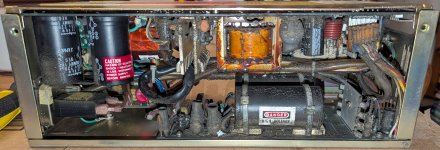
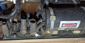
I am not sure what the black "gunk" was that was all over the inside, and in retrospect trying to clean it out with IPA and swabs was not the greatest idea. I liked the idea of a compressor, but due to lack of space, I ended up buying an electric (plug-in) blower -- a small hand-hold 90CFM pretty powerful thing. The blower blasted most of the gunk out of the way.

I ended up separating the three boards in the power-supply (H7864A), replacing the three RIFA capacitors, some of which had visible cracks in the plastic casing. I ended up tracing out and drawing the schematics for the ac/dc PCB with the large caps. Happy to share if anyone is interested?

It took a bit of time to get my hands on SL-156 connectors, pins and a working crimping tool, to make a myriad of connectors (i.e. AC/DC converter PCB to banana plugs; power connector from the switching PCB to adequate sized bundled up thick-gauge wire coming out of the PSU to end in 10 AWG wires to lugs to be connected to load resistors).

I then proceeded with reconditioning the caps using a variable AC power supply (0-140V ac / 2A) with the switching PCB disconnected, with a relatively small load resistor (300ohm/200W) connected serially with an incandescent light bulb across the 250V DC output of the PCB, going in steps by increasing the AC input by ~20V increments at a time, every 20-40 minutes or so. Once I was running at line power (110V), I let it soak for 8-10 hours, drawing around ~320mA.

Once I finished with the AC/DC converter PCB, I reconnected the switching PCB, and added modest loads to all the DC rails, while I again started from 0V ac input, and increasing the input voltage in steps all over. The switching PCB is doing some interesting things when not fed full line input. Not exceeding any output voltage, but sometimes providing lower-than rated output voltages, and sometimes dropping to 0V. I figured it would still exercise the caps on the switching PCB, even if switching didn't start, so I went slow, and eventually reach full mains input voltage. Switching started at some point around 70-80% of full input voltage, and the output voltages became much more consistent above that. Once I reached 110V, I again let the PSU "soak" for a longer while, still using fairly modest loads.

I then proceeded to put the PSU back together, and install the fans (but otherwise an empty BA23 enclosure). I then progressively started out, running at full input voltage, and progressively increase the load on all the DC rails. I started out with 100-300 ohm With 100W load resistors. I ran each load for 20-40 minutes, then progressively decreased the load resistance. I took down some notes when I reached more significant loads:

With a 2.5 ohm/300W load resistor on the 5V rail, it draw 2A. Voltage = 5.1V, Both fans running. POK and DC OK both high. Draw 0.7A from mains.
With a ~0.7 ohm/300W load resistor on the 5V rail, it draw 7.0A. Voltage = 4.97V, Both fans running. POK and DC OK both high. Draw 1.0A from mains.
With a ~0.5 ohm/300W load resistor on the 5V rail, it draw 10.3A. Voltage = 4.883V. Both fans running. POK and DC OK both high. Draw 1.3A from mains.
With a ~0.2 ohm/300W load resistor on the 5V rail, it draw 20.5A. Voltage = 4.610V. Both fans running. POK and DC OK both high. Draw 1.9A from mains.

At this point I was a bit concerned about the voltage drop on the 5V rail, and tried to figure out what was going on. I realized that I had spliced all 5V connectors into a single 16 (or perhaps 14) AWG wire which had enough resistance at these higher loads to cause the voltage drop. I replaced cable in my test connector with a 10 AWG, and continued with the last load:

With ~0.15 ohm/600W (parallel) load resistors on the 5V rail, it draw 33.1A. Voltage = 4.988V. Both fan running. POK and DC OK both high. Draw 2.8A from mains.

This output voltage on the +5V rail made me a lot more comfortable!

I let it "soak" drawing 33.1A for a good a good while (many hours). This is close to the max. current draw on the +5V rail. The air from the fans would become pretty warm. The PSU itself became warm, but not alarmingly so.

After successfully running the PSU for a long good while, I resinstalled all the boards, the harddisk, the RX50 floppy, and connected up a laptop running tio, Speed set to 9600bps, and powered it on!

AMAZINGLY, it powered on, performed the usual memory self test, and stopped at the prompt (as I had set it to do). I checked the memory map, the device list. The harddrive had spun up as well, so it seemed there was more life in the PDP than I could ever have hoped for! On a whim, I tried to boot from the harddrive, not having much hope that it would actually work, or that the hard-drive, if working, would actually have any useful OS on it to boot; but to my surprise it proceeded booting up an old version of RSX-11M!!!!!!!

It is a bit of a weird system though. The RSX installation is pretty stripped down, and it's running a bunch of weird AT&T device drivers and random tasks. Inspecting some of the *.cmd files, gives me the impression that the PDP was used to monitor or control some aspect of some kind of printing plant. Not sure exactly what, but I dumped the harddrive overnight via dump, to preserve it.

Once I ensure that the current system is copied off correctly, I will get XXDP+ on it, and run all the 11/73 tests I can find, before I proceed to reformat the hard-drive and install a new copy of rsx!

I am still amazed that the entire PDP in it's entirety, including the hard-drive is working perfectly fine. Granted I have not yet tested the RX50 floppy. I am on the look-out for an old floppy controller to format some old DD floppies to try with, but I am not in a rush.

Throughout the process of cleaning the PDP, replacing the RIFA caps, and reconditon the other caps, I took a pretty large number of photos (~400) to document everything, including cables, connectors, pin-outs, PCB traces and components markings to keep as a record for putting it back together and in an attempt at trying to reverse-engineer parts of the PSU. I am happy to share any of those photos if there is interest?

A huge thank you to all of you for your helpful comments and helpful tips on how to go about and doing a PSU restoration!

/Jörgen
 
That's a good process there! - If you have made sense of the adjustable fan regulator part of that board, I would love to see your drawing - I change the 3 series resistors to 6K8 to get about 7 - 12V adjustment with the existing link and with new 185cfm fans, this works well...

I would soak test it on XXDP and VMSA for a few hours to weed out any early memory issues after all this time

Robin
 
Robin,
Sure thing. I am attaching one of my notebook pages, that includes my cleaned up schematics of the adjustable fan regulator towards the bottom of the page. I meant to create a KiCad schematics, but have not gotten around to it yet.

Jörgen


H7864 Power Supply page-4.png
 
Hi Jorgen - That is great work, thanks! - the presence of the -15V supply just for the fans was a surprise when I found it - in the later DEC version of the supply (The -B version) they use 2 x LM337T, one per fan but with common adjustment, and the -ve rail is regulated, with fan +ve going directly to ground, the opposite to here with the +ve LM317 regulator...

I was thinking of creating a Repair thread for the -B version where we could collate info like this - Maybe good to have a thread for each version, especially if you have found any good faults?

Thanks again,
Regards, Robin
 
Robin, I am actually in possession of two H7864-B PSUs, that are sitting in my basement waiting for me to start the restoring them, so the timing is good for starting a new thread for the -B variant.

I can't say I have found real faults. Some oddities perhaps, like the orange/white wires for the remote control seems to be switched in the panel-mounted connector, compared to the connector on the PCB (i.e. white -> orange; orange -> white), but that could just have been someone having done work on the PSU previously, and in either case, it shouldn't matter since there is no polarity that you need to pay attention to in the remote power connector, as far as I know.

Regards,
Jörgen
 
I am interested in the compressor idea but I don't really know what exactly to look for. Could someone share a link to the kind of product you mean please? I did buy myself a hand held blower that is supposed to be for cleaning computers, it sort of does the job but it isn't all that powerful.
 
Back
Top