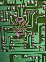
According to the schematic of the TDA1170, pin 1 to pin 12 is two base/emitter junctions so 12 should be slightly lower than 1 but your voltages are the opposite.
Also pin 11 is only .1 when a .6 volt signal should be there. I think IC401 needs to be replaced.
I agree the IC is a possibility. However the most likely part internal to the IC to fail, is the output stage transistors. The one in question is the Szlikai pair that is responsible for sinking current in the lower leg, rather than the Darlington in the upper leg.
Yet, there is one measurement that suggests that the output stage is ok, and that the output amplifier is ok, that is the pin 4 voltage, being, on the average about 1/2 the supply voltage.
I think the OP should buy an IC as a spare anyway in case it is needed.
The problem could still be elsewhere.
One thing, if the OP measured the DC resistance of the yoke vertical coils with the meter. And somebody on the forum could do the same on another 5151 (I don't have one of these VDU's) then we could rule out one of the V coils being open circuit.
The problem would be very easy to sort out with a scope. On the balance of probabilities though, it is more likely the IC. But, it is not good when an IC gets needlessly replaced because other avenues were not exhausted first, but those avenues are blocked to a large extent without a scope. Though, in the Song Feel My Love, Bob Dylan was willing to crawl down the Avenue, and his son Jakob in the Wallflowers, was willing to drive home on "One Headlight", so it is amazing what you can sometimes do without test gear.