• Please review our updated Terms and Rules here

IBM 5151 Monitor

This makes much more sense to the layperson.

If that resistor on the yoke is R403 no wonder I couldn't find it. I was looking on the pcb. Its resistance = 4.2ohms. I also saw the number 1 and 2 on the white piece of plastic. NOW it makes sense. ;-)
Pin 2 = 14.47v
Pin 5 = 13.92v

If waveforms are next and Hugo assists in me finding a decent, not too expensive scope what exactly will the waveforms diagnose? Does this mean cutting the glue on the yoke against the tube, adjust the yoke and then re-glue it with the power turn on? I do have electrical insulated rubber gloves but never used them!!! ;-)

Don't do things like cutting glue and removing the yoke.

What you are interested in is to confirm that the DC resistance of the V yoke coil combination closely matches that of other 5151 VDU's, which you have done and got 4.2 Ohms,so forget about the yoke being the problem for now, and concentrate on why, as the scan progresses the current is not rising at the rate that it should toward the bottom of the raster screen.

I mentioned the possible causes.

(A yoke with shorted turns in one of the two windings would be expected to have a lower DC resistance than normal and if one of the two windings was open circuit, since they are in parallel, one would expect the DC resistance to be double that of the standard value, so it looks the the yoke is out of the equation).


A high resistance connection in the wiring leading to the yoke (double check the DC resistances). A High ESR or wrong value yoke coupling capacitor could do it. Are you sure this replacement capacitor is suitable ?

Now we know the IC is ok, and the power output stage in the IC is ok (remember I suspected it was because the DC voltage on the output was about right), there are really only two other possibilities. One is that the power supply to the IC is sagging down during the V scan, you could see that on a scope, but probably not wonderfully likely with the meter voltages you have measured.

The other is, that the output stage of the IC is being presented with an incorrectly shaped drive waveform (the output amplifier in the IC can only reproduce the drive wave it is being fed with), and what you are seeing on the screen is simply a manifestation of that . The drive wave is supposed to be basically sawtooth looking. This is where the scope comes in handy, comparing the waves with what is shown on the previous documentation and also checking the dynamic stability of the power supply voltage. To do this latter test the scope must be set on DC coupling.
 
Last edited:
This is where the scope comes in handy, comparing the waves with what is shown on the previous documentation and also checking the dynamic stability of the power supply voltage. To do this latter test the scope must be set on DC coupling.
In support of an earlier thread, I made some of my own oscilloscope measurements, putting them at [here].

My measurements show the DC component. I'll add some more; more pins of the TDA1170, including the various DC supply ones.

A High ESR or wrong value yoke coupling capacitor could do it. Are you sure this replacement capacitor is suitable ?
Inserted in the wrong polarity? I wonder what that would do.
 
A High ESR or wrong value yoke coupling capacitor could do it. Are you sure this replacement capacitor is suitable ?
Being the neophyte/ green guy here I'm not sure what capacitors you guys are referring to so I made a guess. I replaced a neck board cap C204 with a 50v 1uF, and following a wire from the DC resistance resister on the yoke to the board I double checked the cap next to the connector: C408 10v 2200uF. Polarity is correct for both. This was a kit, so I only replaced what was in the kit, and not based on my knowledge of this 5151. ;-) If I should check a different cap please let me know.
 
Being the neophyte/ green guy here I'm not sure what capacitors you guys are referring to so I made a guess.
Sorry about that. The reference was to C408, the cap that couples the TDA1170 output to the coils. I confirmed that in my 5151, the cap is 2200uF/10V.

This is where the scope comes in handy, comparing the waves with what is shown on the previous documentation and also checking the dynamic stability of the power supply voltage. To do this latter test the scope must be set on DC coupling.
In support of an earlier thread, I made some of my own oscilloscope measurements, putting them at [here].
My measurements show the DC component. I'll add some more; more pins of the TDA1170, including the various DC supply ones.
Done.

... and also checking the dynamic stability of the power supply voltage. To do this latter test the scope must be set on DC coupling.
Per [here], I measure about 200 mV on my good 5151.
 
If you guys can recommend a scope (that's a good one) but it's not too high I will consider buying one. Please first educate me on the next step if the readings I get are way off. What's the necessary repair? Then an approximate of the cost + a scope. I do like having the 5151 but $600 investment in repairs, well it might be tough to justify, but I have been known as a spontaneous spender. ;-)
And I very much appreciate all you guys have helped on this. Been educational. I suppose it's like M7 says "The day I stop learning is the day I drop dead," hopefully not too soon!!!!!
 
Another quick note; if it's an adjustment/fix someone green can do I will most willing to attempt it with your suggested tweak.
 
If you guys can recommend a scope (that's a good one) but it's not too high I will consider buying one. Please first educate me on the next step if the readings I get are way off. What's the necessary repair? Then an approximate of the cost + a scope. I do like having the 5151 but $600 investment in repairs, well it might be tough to justify, but I have been known as a spontaneous spender. ;-)
For this, you won't need an expensive oscilloscope.

But let's say that you buy an inexpensive one (after further discussion here), learn how to use it, record and post here what the oscilloscope shows on the various pins of the TDA1170, and a diagnosis continues from there. We know that the TDA1170 is good, the vertical deflection coils (and associated anti-ringing resistor, R413) are good, and so if you look at the circuit diagram at [here], everything else to the right of an imaginary line running through the TDA1170 between pins 2 and 12, is either a resistor or capacitor (or solder joint). And none of those are special, and so the replacement component cost has to be small.

( BTW. I added a {TDA1170 pinout as viewed from solder side} photo to [here]. We have seen newbies get the pinout wrong, which 'leads us down the wrong path' until it gets picked up. )

Before (or in parallel with) getting an oscilloscope, I wonder if it is worthwhile replacing C403 and C403. They are fundamental to vertical linearity. You checked their capacitance value as okay in post #8 ("C403:155nF C404:158nF") but I am reminded about what @retrogear later wrote at post #35: "You may have to replace C403 and C404 if R404 is ok. I remember those damn green caps like to go leaky with resistance."
 
You may have to replace C403 and C404 if R404 is ok.
I will replace C403 and C404 after checking R404 if that's suggested.
We have seen newbies get the pinout wrong, which 'leads us down the wrong path' until it gets picked up
I admit I'm as green as it comes and newbie when it comes to popping the hood of a monitor, but not to computers, ICs and soldering and many other exposures. I've retired 33 years IT (half my life), first 13 years were PC & Server builds PC support along with NOS builds (NT, Novell), Cobol, Basic, Fortran, Perl, HTML programming, replaced 100s or more of ICs in my time, built and sold PCs on the side, the last 20 I was employed with the Federal Court systems as there senior Linux SA and senior Informix DBA doing server builds as well maintaining the 4th largest bankruptcy court server in this beloved country, worked with switches, MAUs (older days) and I could go on. Been doing component level repairs on Commodore, Coleco, PCs, and other game consoles for around 11 years. Gained much hands on with 5150 lately too. Granted my component level repair experience doesn't match most others on this site, but imho "newbie" and strong understanding of what Pin 1 is for no newbie here. Re: the 5151 I checked the legs three times before soldering it on the PCB. Yes I said the legs were tricky getting them all lined up to the holes because they're not parallel to each other I didn't mean I didn't understand the pin 1 practice. The defacto standard for me is check 3 times before soldering or twice before inserting into a socket. A socket screw up is simple: replace the chip that was burnt but nobody wants to desolder and then resolder unnecessarily, hence triple check. I would bet if I reversed the TDA1170, which I know I didn't, my guess it would've burned out by now.
 
Been educational. I suppose it's like M7 says "The day I stop learning is the day I drop dead," hopefully not too soon!!!!!
I did expand a little on that at [here].

I admit I'm as green as it comes and newbie when it comes to popping the hood of a monitor, but ...
I only remember the experience/knowledge levels of 'well known players' here, e.g. like Chuck(G), Eudimorphodon, and Hugo Holden.

When it comes to 'newbie' status, I'm definitely one of those for Apple products (including cell/mobile phones). On a zero to ten scale, I'm a zero. Although, I can spell Apple, so maybe that gets me to 0.2

I will replace C403 and C404 after checking R404 if that's suggested.
I remember fixing a DEC LA120. At power-on, the carriage would slam hard to the right. The various diodes showed good on the diode test of a multimeter, but one diode turned out to be leaky.
 
Hello everyone.
Ok just replaced C403 and C404 with 15uF 50v NP Polyfilm caps and the same. I crossed my fingers too.
Thank you very much for your help with this old guy - the 5151.
I'll consider any other ideas.
 
Ok just replaced C403 and C404 with 15uF 50v NP Polyfilm caps and the same.
Oh well.
And I'm sure that you meant 0.15 uF

I'll consider any other ideas.
Before heading down the acquire-and-learn-how-to-use-an-oscilloscope route:

In the circuit diagram at [here], if we put an imaginary vertical line running through the TDA1170 between pins 2 and 12, there is not much to the right of that line.
You could use a multimeter to verify that the components in scope are connected together per the diagram.
For the resistors, you could cut a leg (i.e. effectively taking the resistor out-of-circuit), measuring the resistor, then blob soldering the cut.
 
And one discrepancy that I did not see followed up on was in regard to VR403 (the vertical linearity pot).
See posts #6 and #7.
A mismeasurement ?
 
You could use a multimeter to verify that the components in scope are connected together per the diagram.
Do you mean test continuity?

See posts #6 and #7.
I'll re-read these posts.

And I'm sure that you meant 0.15 uF
Yes, sorry for the mistype.

For the resistors, you could cut a leg (i.e. effectively taking the resistor out-of-circuit), measuring the resistor, then blob soldering the cut.
Do you mean cut a leg on those resistors to the right of imaginary vertical line between pin 2 and pin 12 or one or two? If I counted that's 8 resistors.
 
You could use a multimeter to verify that the components in scope are connected together per the diagram.
Do you mean test continuity?
Yes, to detected bad solder joints and open-circuit traces.
For example, from the circuit diagram, I know that I should measure 0 ohms (up to say, 2 ohms) between one of the legs of R409 and one of the legs of R411.

For the resistors, you could cut a leg (i.e. effectively taking the resistor out-of-circuit), measuring the resistor, then blob soldering the cut.
Do you mean cut a leg on those resistors to the right of imaginary vertical line between pin 2 and pin 12 or one or two? If I counted that's 8 resistors.
The problem with doing resistance measurements of resistors when they are soldered in, is that you are often measuring more than the resistor. It depends on the circuit. Doing that, you will either read close to the resistor's resistance, or something lower. If you read the latter, you will not know if the resistor is at fault, or if the low measurement is due to the resistor being measured in-circuit.

So, by taking the resistor out-of-circuit, you know that you are measuring only the resistor. You could completely remove the resistor from the PCB, but 'lifting' one leg is enough. Also, cutting one leg is enough - see [here].
 
Sorry been very busy lately and haven't had the time to get back to you. Hopefully very soon I can get back to this.
 
Sorry been very busy lately and haven't had the time to get back to you. Hopefully very soon I can get back to this.
No need to apologize. This is a hobbyist environment. It's all very low priority. I have broken stuff that has been put aside for many many months.
 
LOL.

Ok I started from R404 touched a leg of C403 - continuity, but with the probe on the same leg of R404 I touch either leg on C404 no continuity. I shouldn't get anything from the earth leg right? If I'm seeing the schematic right one leg of R404 goes to earth as is one leg on C404. I'm not using the earth leg for testing. Also I'm not mentioning anything about the other components down the line because I haven't gotten passed getting continuity from R404 to C404. It looks like I should get a continuity read from R404 to C404 right?
 
Ok I started from R404 touched a leg of C403 - continuity, but with the probe on the same leg of R404 I touch either leg on C404 no continuity.
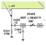
The relevant part of the circuit diagram is below. No continuity is expected between R404 and C404 - those two components are not directly connected to each other.

R404 example:
- One end is grounded, and so one of the legs of R404 is expected to have continuity to ground. You would verify that continuity.
- The second leg is directly connected to pin 12 of the TDA1170, and so you would verify that continuity.
- The second leg is also directly connected to one of the legs of C403, and so you would verify that continuity.

C403 example:
- One leg has a direct connection to R404 and to pin 12 of the TDA1170, but we know from the R404 measurements, that those connections are good.
- The second leg is directly connected to one of C404's legs, and so you would verify that continuity.
- The second leg is also directly connected to one of VR403's legs, and so you would verify that continuity.

1707027494672.png
 
BTW. If you remove the board from the chassis, the traces on the solder side of the board will inform you as to which leg is what. If you decide to do that, you should still do the measurements on the component side (i.e. probe on legs), because bad solder joints (besides open-circuit traces) are also being looked for.
 
Back
Top