• Please review our updated Terms and Rules here

IBM 5155 with Optional Raspberry Pi

DrAlis

Experienced Member
Joined
Nov 11, 2021
Messages
216
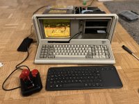
Gents, I would enjoy your thoughts on an idea I wanted to try with an extra working IBM 5155 I have:

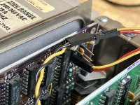
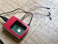
I was thinking of hiding an extra Raspberry Pi 3 Model B (RPI) inside somewhere and feed its' composite output from the 4 segment jack to the mono CRT input by feeding into the connector usually sitting on the CGA card. Power for the RPI is taken from a drive bay power connector. Also, I would like to feed the XT keyboard into a soarer and then into the PI as well. I'll keep the original stuff in there to create load for the power supply. So some questions for you:

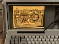
(1) Will the RPI composite work in the CRT and look good? (CGA got 200 lines? how many lines will the RPI produce?)
(2) Any ideas on how to make it all switchable (original XT and RPI) easily? I'd need a single switch on the back that changes the composite from one source to another and the 4+ lines of the keyboard. Is there a simple hardware piece I can solder everything to that does that? I was considering just having a switch for the video and having the soarer piggyback on the DIN connector on the XT mainboard. After reading some I think this will not work as the keyboard is not talking as unidirectionally with the system as I thought.
(3) Any ideas on if/how to make this better or cooler?

Thanks!
 
Ok, so it seems I have to get/set the RPI to output 15.75 kHz NTSC composite and I should be fine. Colorburst is filtered by the CRT assembly as far as I understood it. For the switching I will get an 8PDF locking switch. Has nobody done this or similar before?
 
RPi composite comes out interlaced so it will flicker a little on a composite TV/monitor. For the Apple II Pi, I did a video that compares a real IIGS to the Apple II Pi running the GSPort emulator on the Pi. Not a very popular video (nobody liked my silent treatment) but if you look closely you can see the difference:

 
Thanks! But took me a while to find if the left or right in your video is the RPI one. I read on the RPI you can switch to progressive NTSC with "sdtv_mode=16". This is also the mode I am hoping the IBM 5155 screen will acccept. Anybody know what the CGA card puts out exactly?
 
Thanks! But took me a while to find if the left or right in your video is the RPI one. I read on the RPI you can switch to progressive NTSC with "sdtv_mode=16". This is also the mode I am hoping the IBM 5155 screen will acccept. Anybody know what the CGA card puts out exactly?
Yeah, the one on the right is the Pi. The IIGS outputs a similar 640x200 non-interlaced signal to the CGA. The lowest resolution I got the Pi to output was an interlaced 640x480 NTSC signal, but you may have better luck with different settings. Although it is a little difficult to see the difference in the video between the two, in person the Pi's NTSC isn't nearly as sharp as the IIGS. But, try it out for yourself.
 
Colorburst is filtered by the CRT assembly as far as I understood it

So far as I’m aware the CRT monitor in the 5155 does absolutely nothing to “filter” colorburst, it’ll just display the color information as luminance like any other contemporary mono monitor. This probably won’t matter much, it’ll just be a little extraneous noise, but if the Pi *has* an option to output pure grayscale that would result in a sharper picture.

The 5155 uses a medium persistence phosphor so an interlaced display mode will probably not flicker too badly, but it also won’t fool anyone if the goal is to pass off this modification as original. Of course, on the flip side I’m not sure what use a 200 line display will be on a Raspberry pi for anything but emulators.
 

Okay, I stand corrected on it having some faculty for filtering the colorburst itself, but look at the waveforms here and you’ll see how the point still stands about how the color information *itself* still interferes with clarity compared to a luminance-only pure monochrome signal.

Filtering the colorburst means you eliminate some dim noise close to the overscan at the beginning of a scan line, but the phase-shifted 3.58Mhz waveform that’s imposed on top of the luma signal still remains. You can’t filter that out completely without reducing the effective horizontal resolution of the screen to something like 227 pixels per scan line. (To filter out the burst you just need to clamp the video output for a fixed period after the horizontal sync pulse.) Here is a post asking if it’s possible to disable color *modulation*, not just colorburst, from the Raspberry Pi’s composite output for this very reason.

The DOS MODE command includes the options ‘bw40’ and ‘bw80’ specifically to disable composite color *modulation* (again, not just colorburst) on CGA cards connected to mono monitors, where the color modulation shows up as obnoxious pinstripes. (If a photo to explain this is necessary I guess I can pull out the machine equipped to demonstrate it.)
 
Last edited:
Thanks for doing the sourcework I should have done properly :) & I will use the BW40 mode idea to improve picture. But happy at first if I see anything at all...

I guess the use case would be using retropi on the cute amber CRT while still having a working original XT at the switch of a button. I am still waiting for my 8PDT switch to arrive before starting the actual mod.

So question for you: Will 640x480 (progressive or interlace) even show anything if the monitor expects 200 lines? I don't know enough how this composite signal works. Or will this just be garbled? I think 480i/p might be the lowest lineage indeed I will get the RPI to. Kind regards.
 
So question for you: Will 640x480 (progressive or interlace) even show anything if the monitor expects 200 lines? I don't know enough how this composite signal works. Or will this just be garbled? I think 480i/p might be the lowest lineage indeed I will get the RPI to. Kind regards.

Unless they’ve done something very specific to the monitor (which is unlikely) it should work fine with either an interlaced or progressive scan. (Interlace is triggered by the vertical refresh pulse being offset by alternate halves of a scan line between paired frames.) So 480i should be fine. (480p would not, that is VGA frequencies, but I don’t think the RPI will physically output that on composite anyway.)

There is a firmware update for the RPI to do 240P; that will make your screen look somewhat more authentic when running emulators, but note the fine print: the display system still looks like a 480 pixel tall buffer, it just never renders half the lines. So, yeah, it’ll give you that fat scanline look, but if you want to use the Pi for anything else it’ll render the screen neigh unusable.

 
UPDATE: Got the Pi connected and was happy to get an image. sdtv mode 16 seems to use progressive ntsc. mode 0 was worse. however image quality is underwhelming especially comparef to 1980s crispness. see images. can this be better?
 

Attachments

  • A3F1378A-D1D5-4B82-A583-9E536AAE6138.jpeg
    A3F1378A-D1D5-4B82-A583-9E536AAE6138.jpeg
    2.6 MB · Views: 28
  • 9E9A80A2-D060-4309-97A4-AFAFB9C737EC.jpeg
    9E9A80A2-D060-4309-97A4-AFAFB9C737EC.jpeg
    2.2 MB · Views: 28
  • B4E96074-8BA9-48EE-91EA-91A43EEF7CC9.jpeg
    B4E96074-8BA9-48EE-91EA-91A43EEF7CC9.jpeg
    2.4 MB · Views: 28
can this be better?

Not really, at least with the built-in composite out on the Pi. As noted, even if you disable colorburst you’ll still get color modulation. If you restrict your color palette solely to shades of pure grey that’s the best you‘ll likely to be able to achieve.
 
Not really, at least with the built-in composite out on the Pi. As noted, even if you disable colorburst you’ll still get color modulation. If you restrict your color palette solely to shades of pure grey that’s the best you‘ll likely to be able to achieve.
Thanks. That is ugly and not worth the mod 😂 
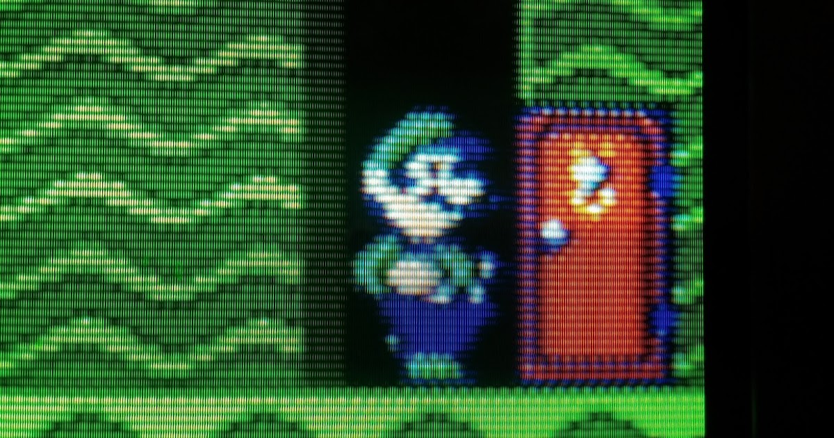
Is there a way to make the RPI or retropie go monochrom? if not i will build back 😢
 
Aaaaaactually, aint that bad!!! IBM 5155 sporting a jumpy Mario!!! Look at this:
 

Attachments

  • 58CD3DE7-E42F-4287-96C2-3D0ED82F12C6.jpeg
    58CD3DE7-E42F-4287-96C2-3D0ED82F12C6.jpeg
    2.9 MB · Views: 27
  • 74A8982F-94ED-424A-BC19-A88FAA89C882.jpeg
    74A8982F-94ED-424A-BC19-A88FAA89C882.jpeg
    3.1 MB · Views: 25
  • 90FC9DFA-C81B-4E7A-96A7-EC085BEF1FD2.jpeg
    90FC9DFA-C81B-4E7A-96A7-EC085BEF1FD2.jpeg
    2.6 MB · Views: 26
So after all a success and nothing was soldered/modified on the 5155. For anyone interested: I used a RPI 3B with 2022 regular retropie image installed. config.txt changing sdtv_mode to 16 and aspect to 4:3. i soldered a 4 pole jack to breadboard cable adapter and connected the pi to the monitor cable with standard breadboard cables. i also wanted to connect the pc speaker to the jack but ended up not doing it as i was unsure if power loads resistance would work for the rpi. have fun.
 

Attachments

  • CC88C2FE-1758-4A5F-8B45-D2ADEF751E72.jpeg
    CC88C2FE-1758-4A5F-8B45-D2ADEF751E72.jpeg
    1.3 MB · Views: 8
  • ABC6F556-0431-45FD-9213-0B54E5367059.jpeg
    ABC6F556-0431-45FD-9213-0B54E5367059.jpeg
    3.2 MB · Views: 8
and on the images cable colors are: red ground / yellow composite / black audio r / white audio l. composite is the 4th pole and ground the 3rd pole counting from the tipp of the jack being the 1st.
 
Back
Top